Milan SL Re-Boomed

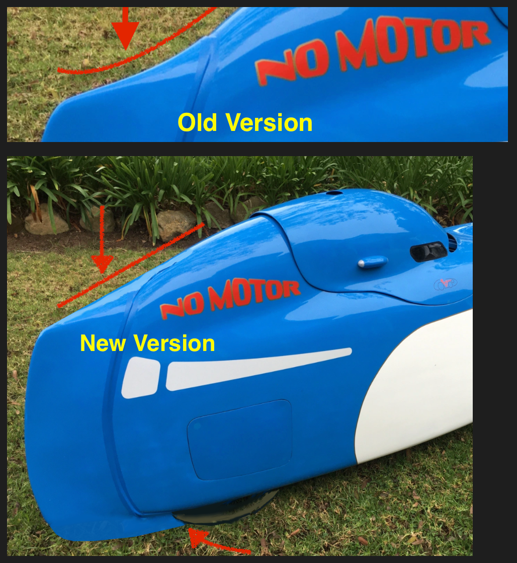
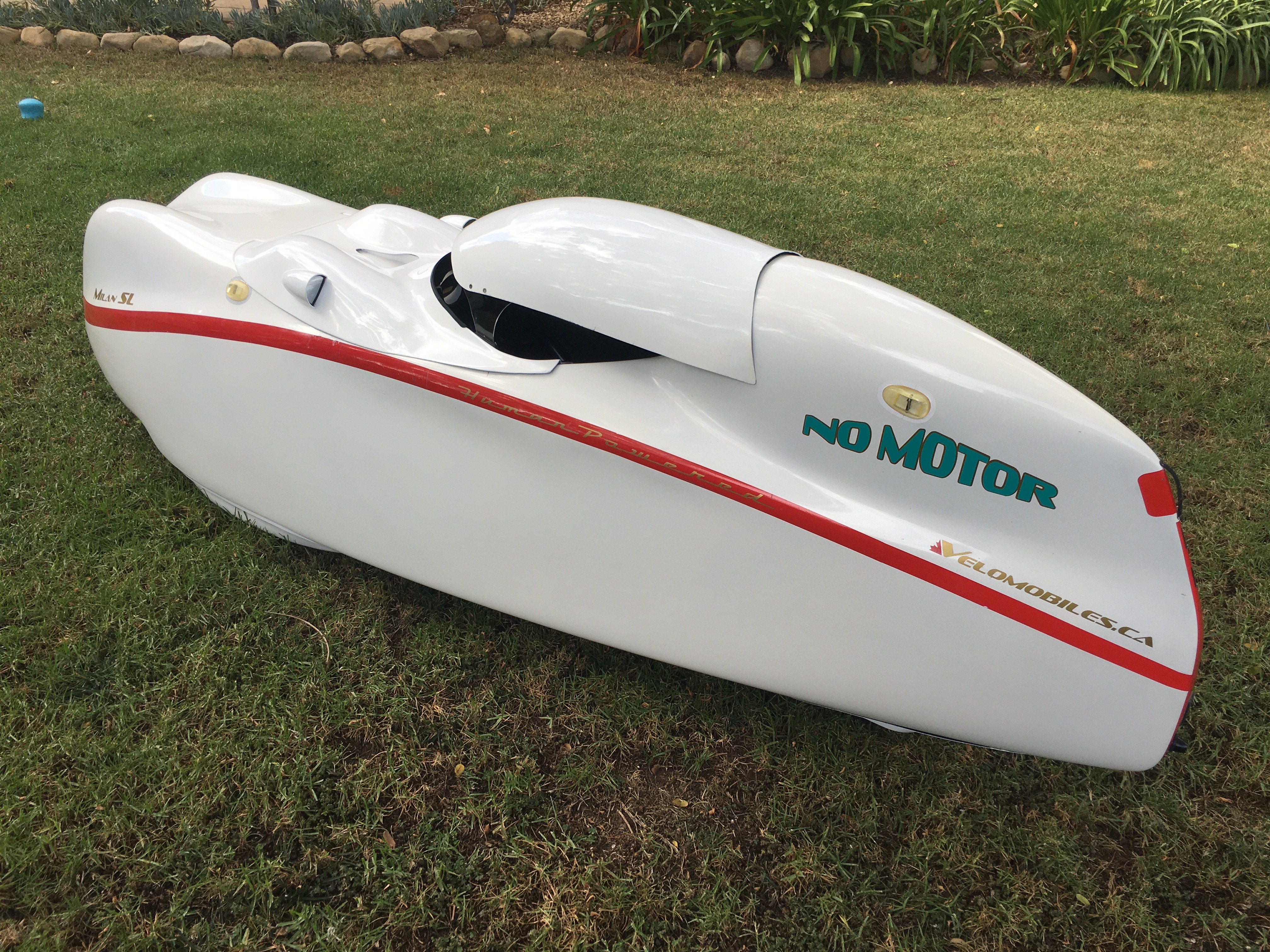
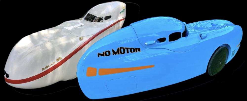
Last July, my Milan SL developed a cracked boom. It probably wasn’t a single event, more like a growing splintering of the sides of the boom. It became evident to me one day when I took off from a stop and my chain came off of the chain ring. This never happens. Upon closer inspection, I could see that, under load, the boom would bend enough to the left to dislodge the chain from the chain ring.

I had a cracked boom on my DF a while ago apparently from over tightening the bottom bracket sled clamps. I was able to successfully reinforce that boom from the inside by laminating carbon fiber and applying pressure using an inner tube as a bladder while the epoxy cured. Unfortunately, the same cure wasn’t available on the Milan. I wasn’t able to work in the interior of the boom tube since neither end of the boom was open. I tried patching it on the outside, then grinding it back down to the 40mm x 40mm square shape required by the bottom bracket sled and clamps. I also added a vertical brace at the cockpit end of the boom and one near the nose of the boom. This whole effort reduced the boom movement under load, but didn’t really solve the problem completely. Back to the drawing board.

I had to bite the bullet and do major surgery. The old boom and added struts had to be removed and replaced with a new boom and supports. With total removal of the old 40mm x 40mm boom, I now had the option of installing a stiffer 50mm x 50mm boom as used on the new Bulk velomobile. So I contacted velomobileworld.com to order a new section of 50×50 carbon fiber tubing, the larger bottom bracket sled and a crankset that fit the new threadless bottom bracket.

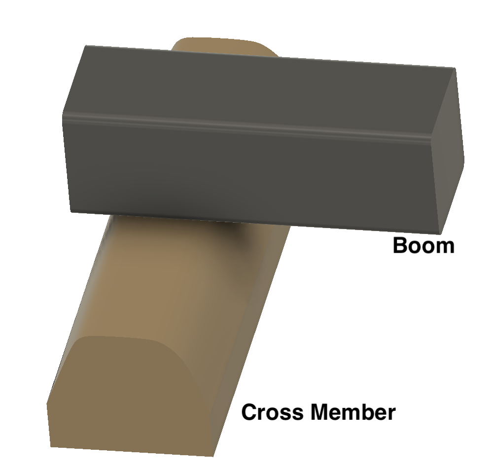
Now the question became how to mount the new boom. Should I remove all of the old structure and redesign the fore and aft mounts? This would also entail redesigning the front idler mount. I opted to leave the existing boom pedestal on the cockpit end. This also serves as the front idler mount. The old boom could just be severed where it joined the pedestal and the new boom could be bonded in the same location. The mounting of the old boom on the nose end was surprisingly simple. It was just laid on top of a cross member in the nose and bonded to that cross member at the intersection. There was no added structure. I could easily cut away the old boom and bond the new boom to the cross member in a similar fashion – although I would end up adding some carbon fiber supports tying the boom to the cross member.

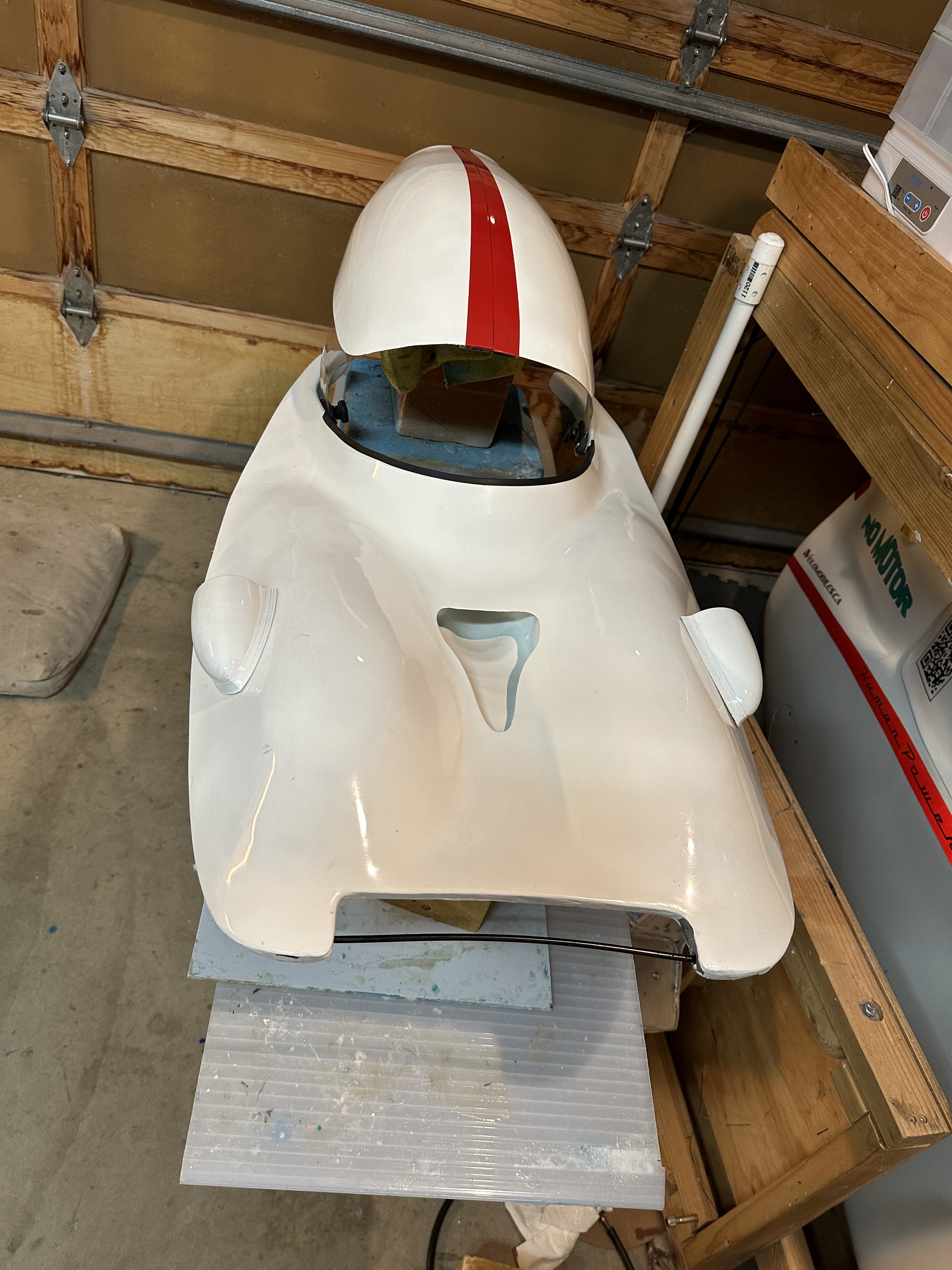
There was one problem looming over the whole project. The Canadian Milan SL was built without any open access to the front half of the interior of the velomobile. Doing surgery in the nose would require longer arms than I posses. There was no getting around the fact that I’d first need to build an access hatch near the nose to remove the old boom and install the new boom.

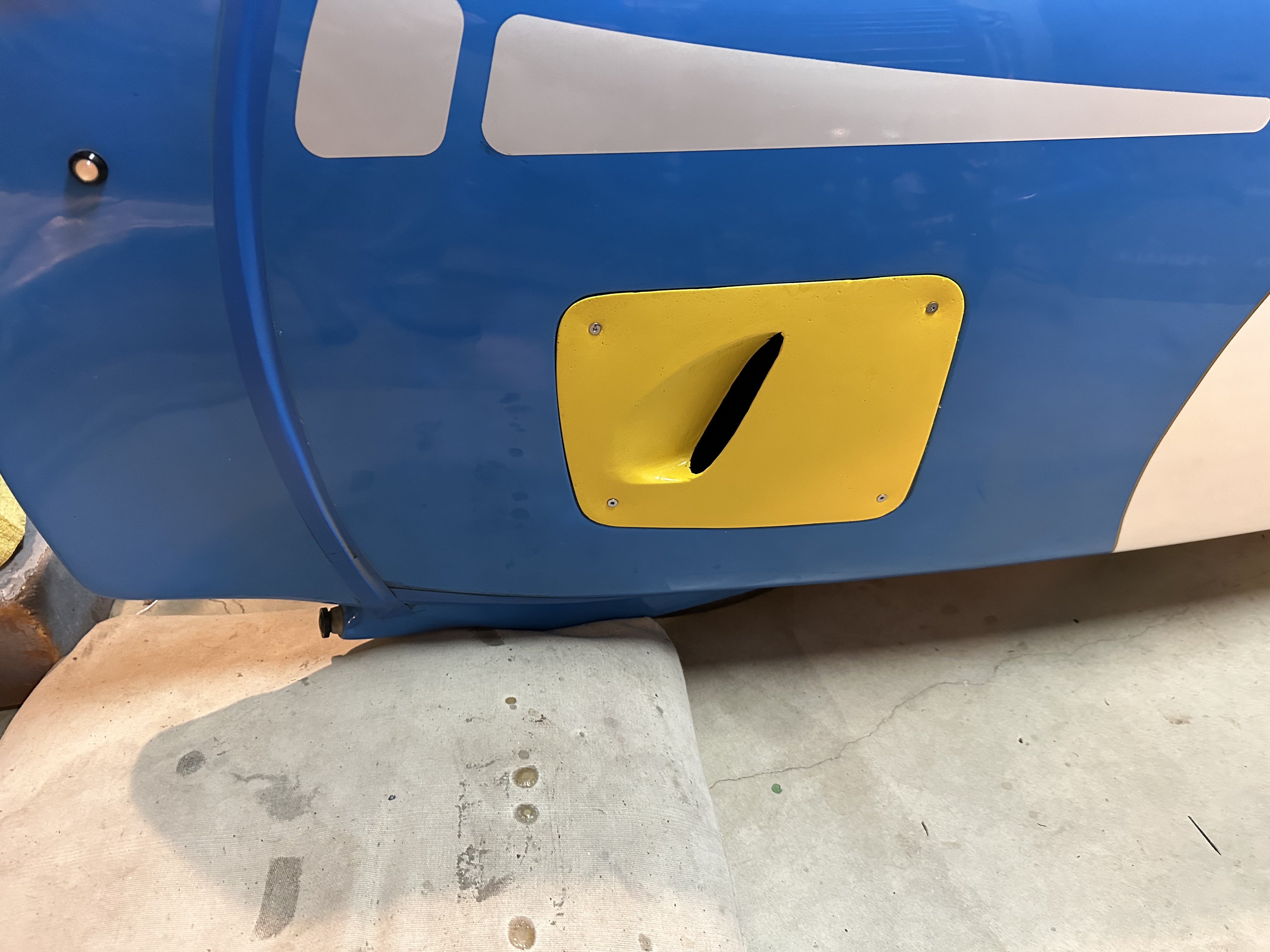
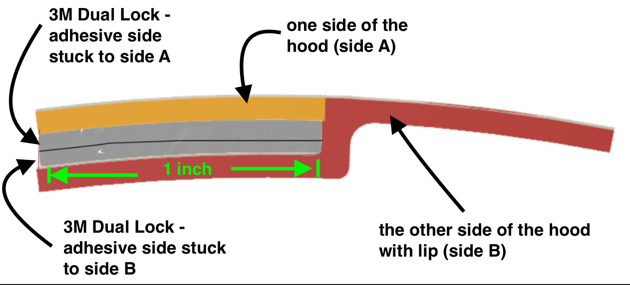
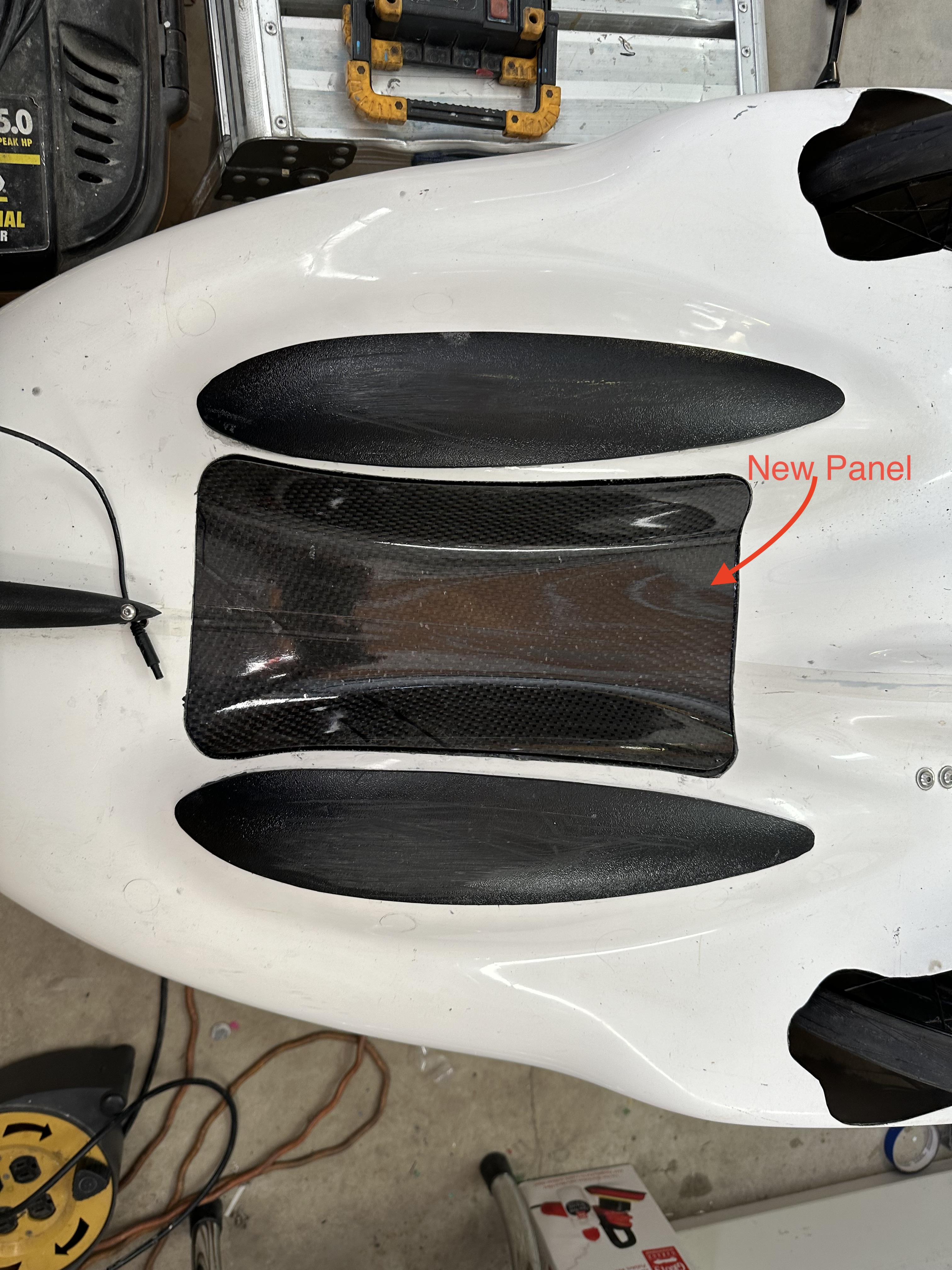
The new opening would need to be reinforced to maintain the strength of the Milan’s shell. It had to have a flush mounted access panel and it could not look like a home made hack job. To give myself a little leeway on that last point, I decided to install the opening out of sight on the bottom of the Milan. The size and shape of the opening were dictated by the structures inside the front area of the cockpit. There were the 2 side luggage compartments, the boom pedestal and the front crossmember to work around.

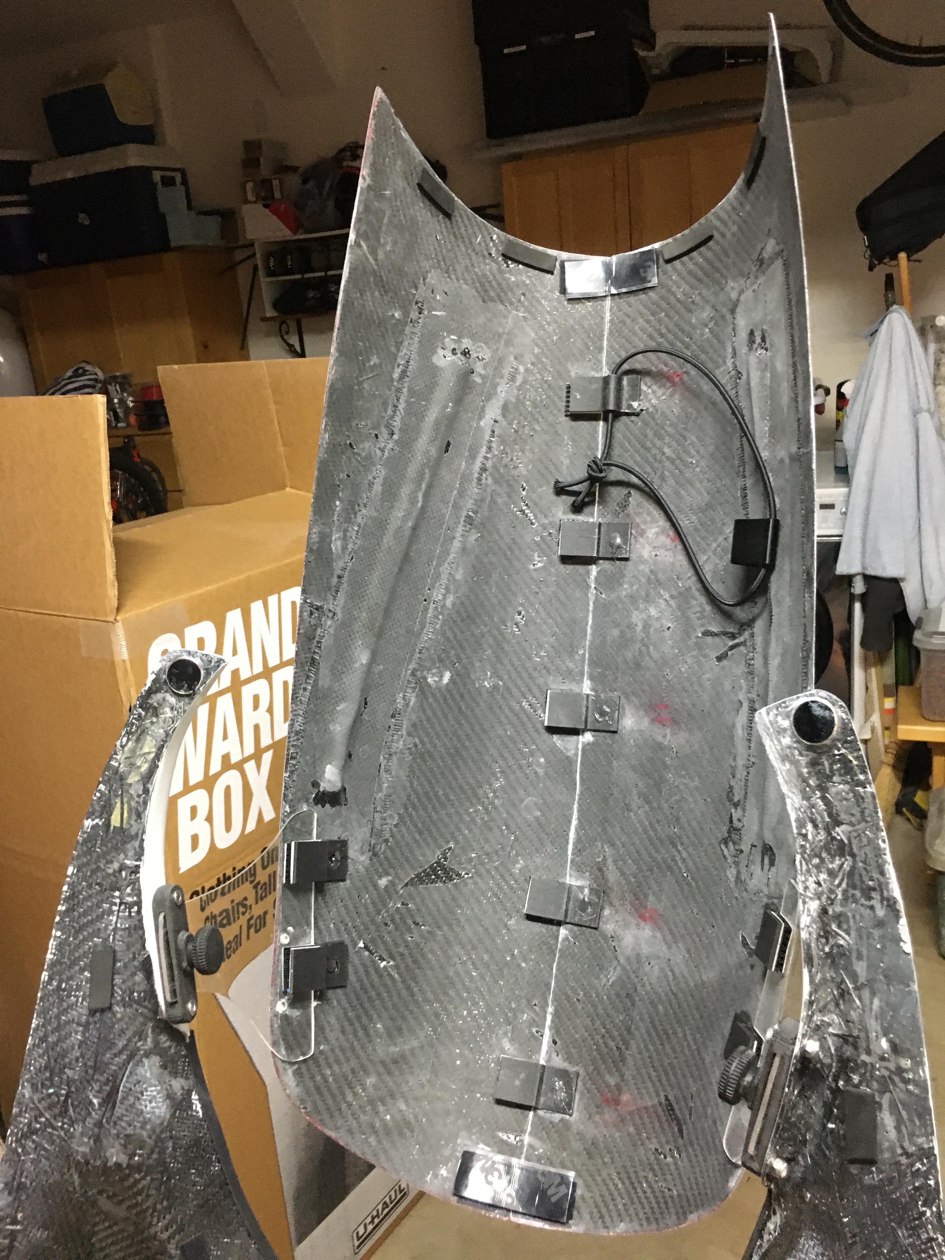
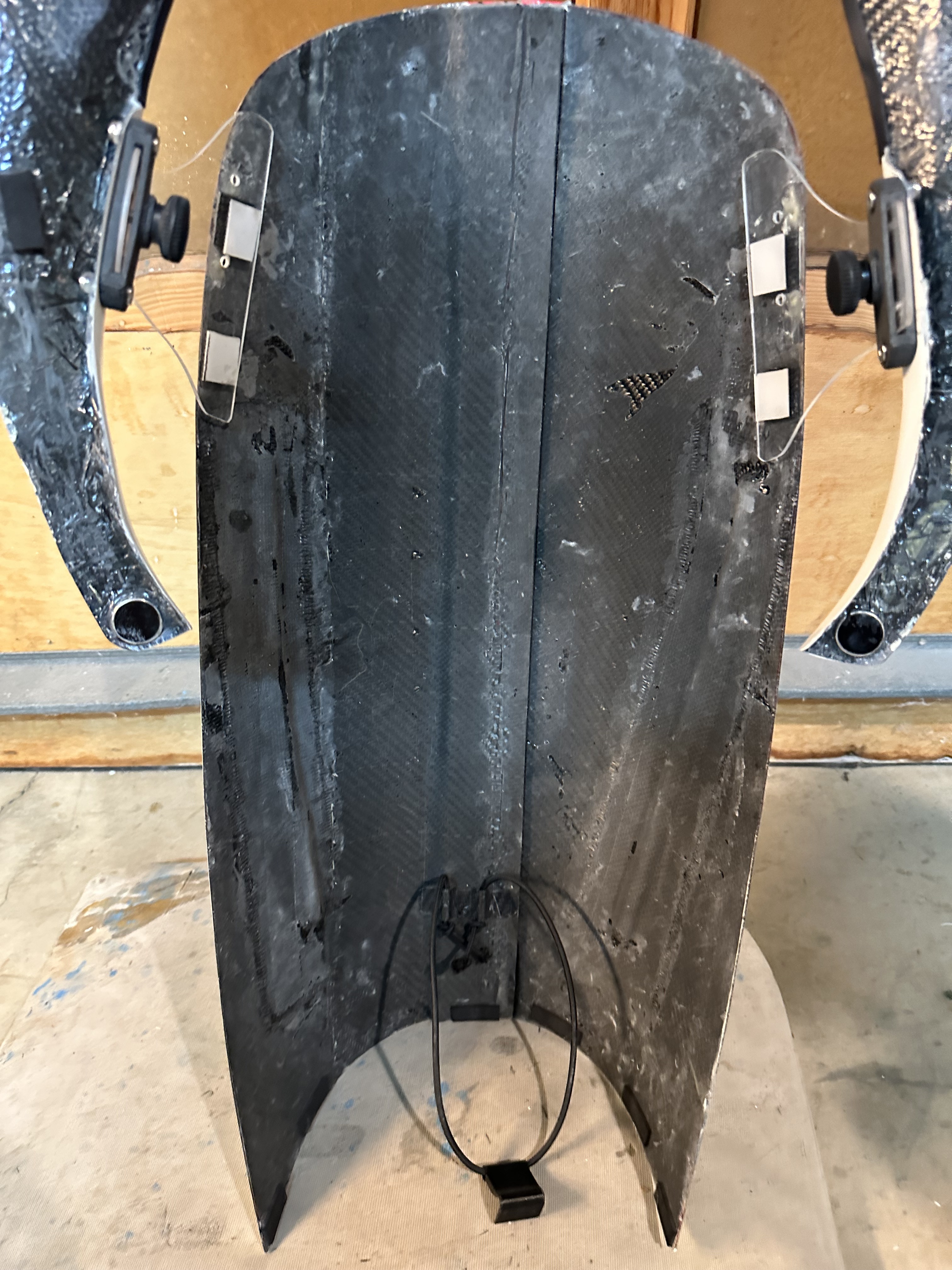
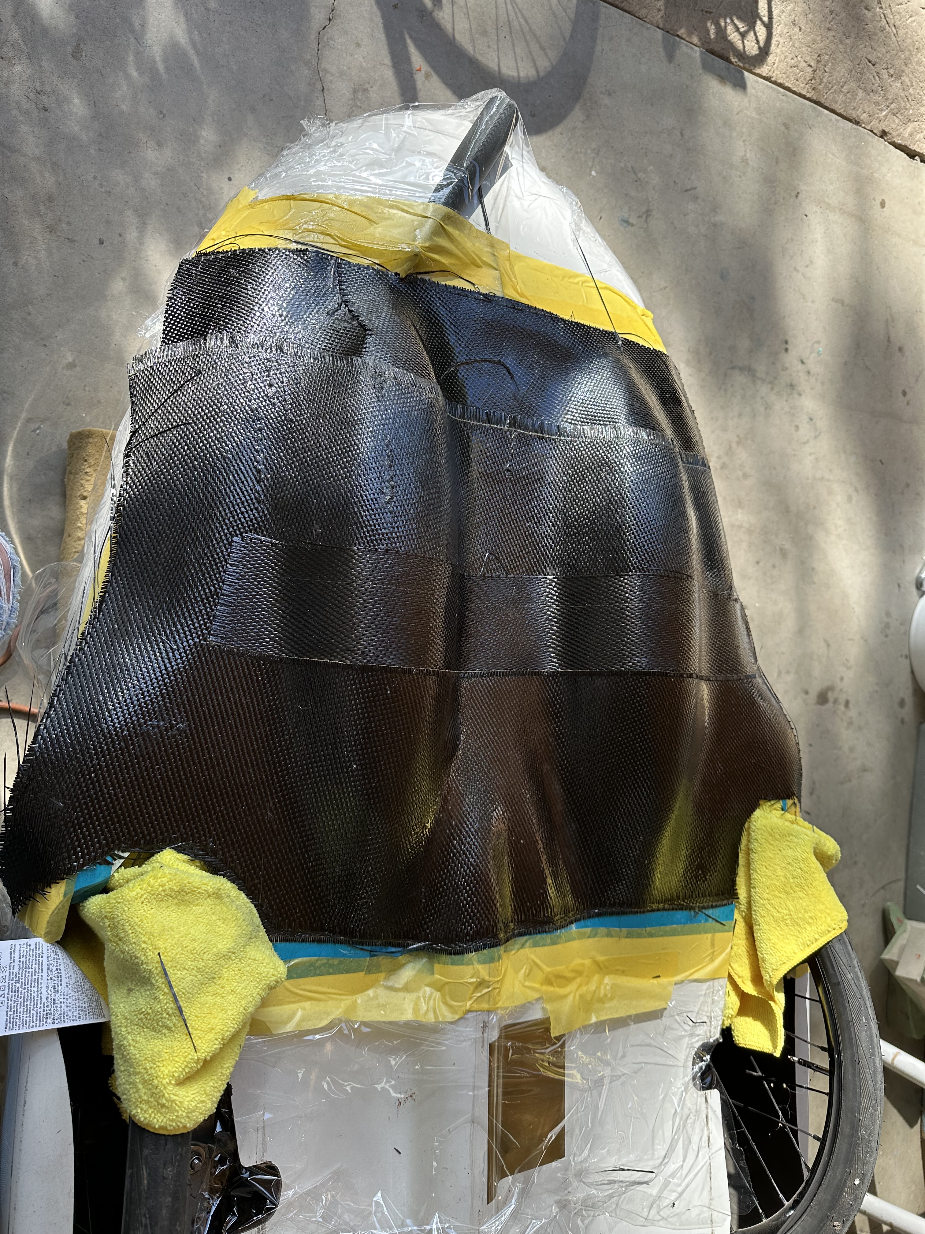
Before doing any cutting, I made a mold of the bottom front portion of the Milan. This would be necessary to construct a reinforcement ring, a flange and an access cover for the opening. This also gave me some extra confidence knowing that I could restore the Milan bottom if I were to totally mess things up.

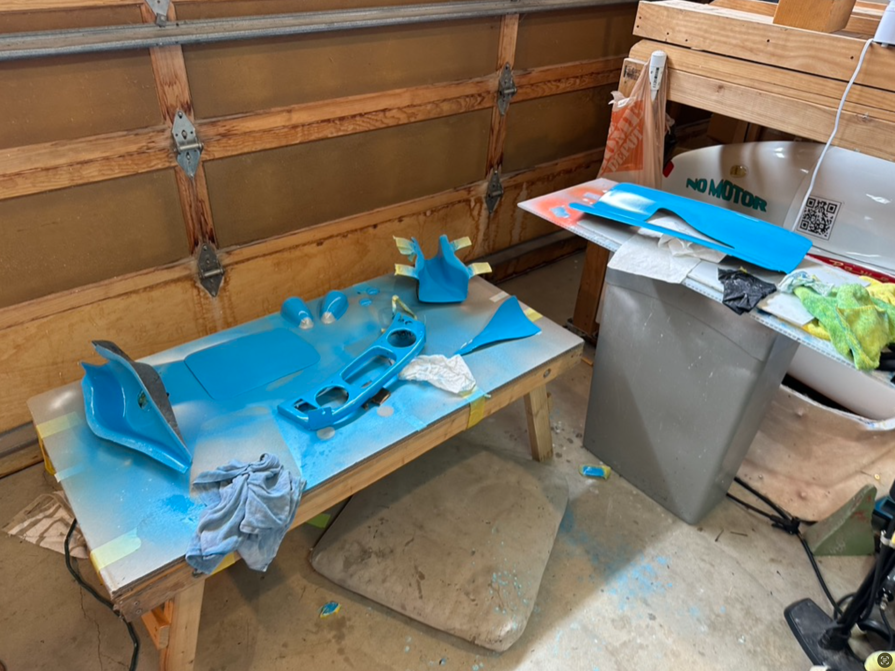
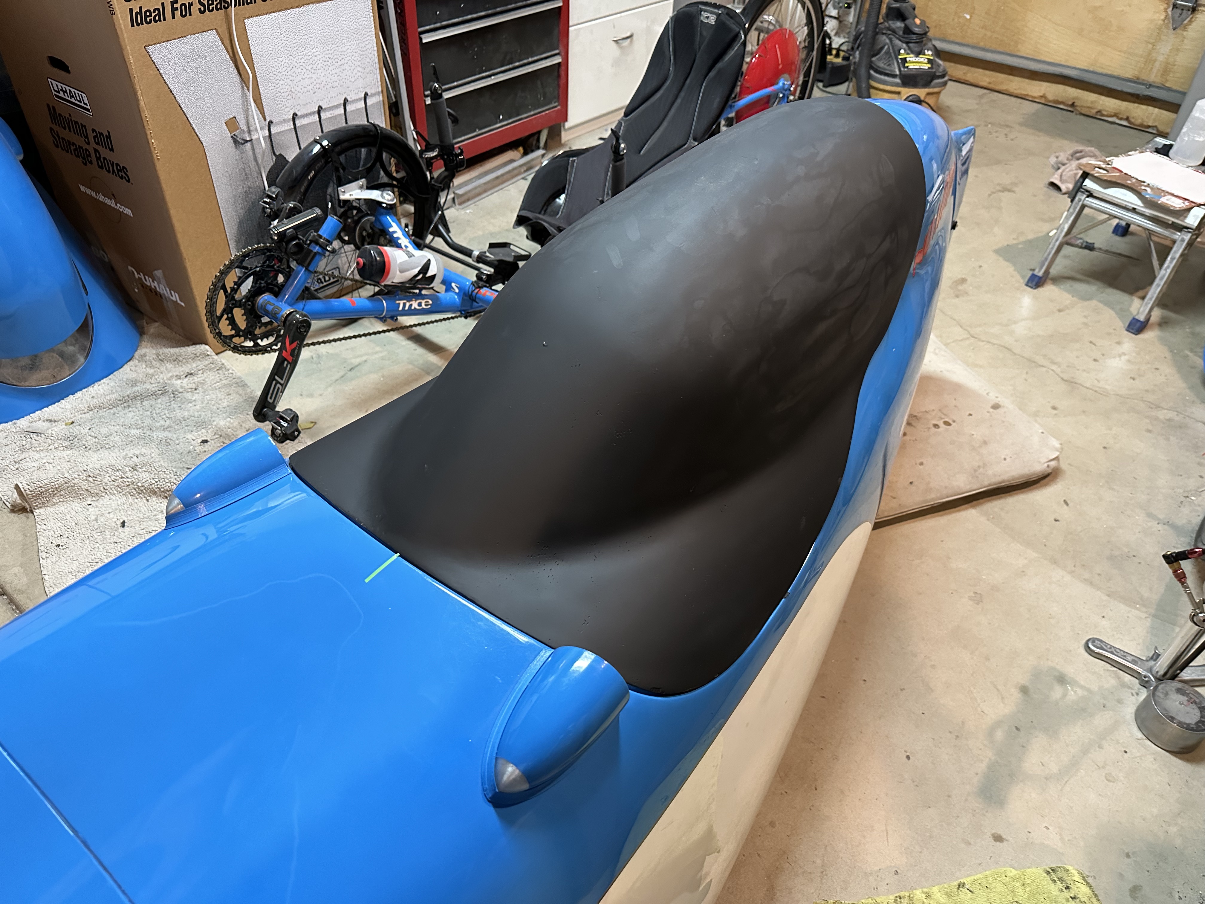
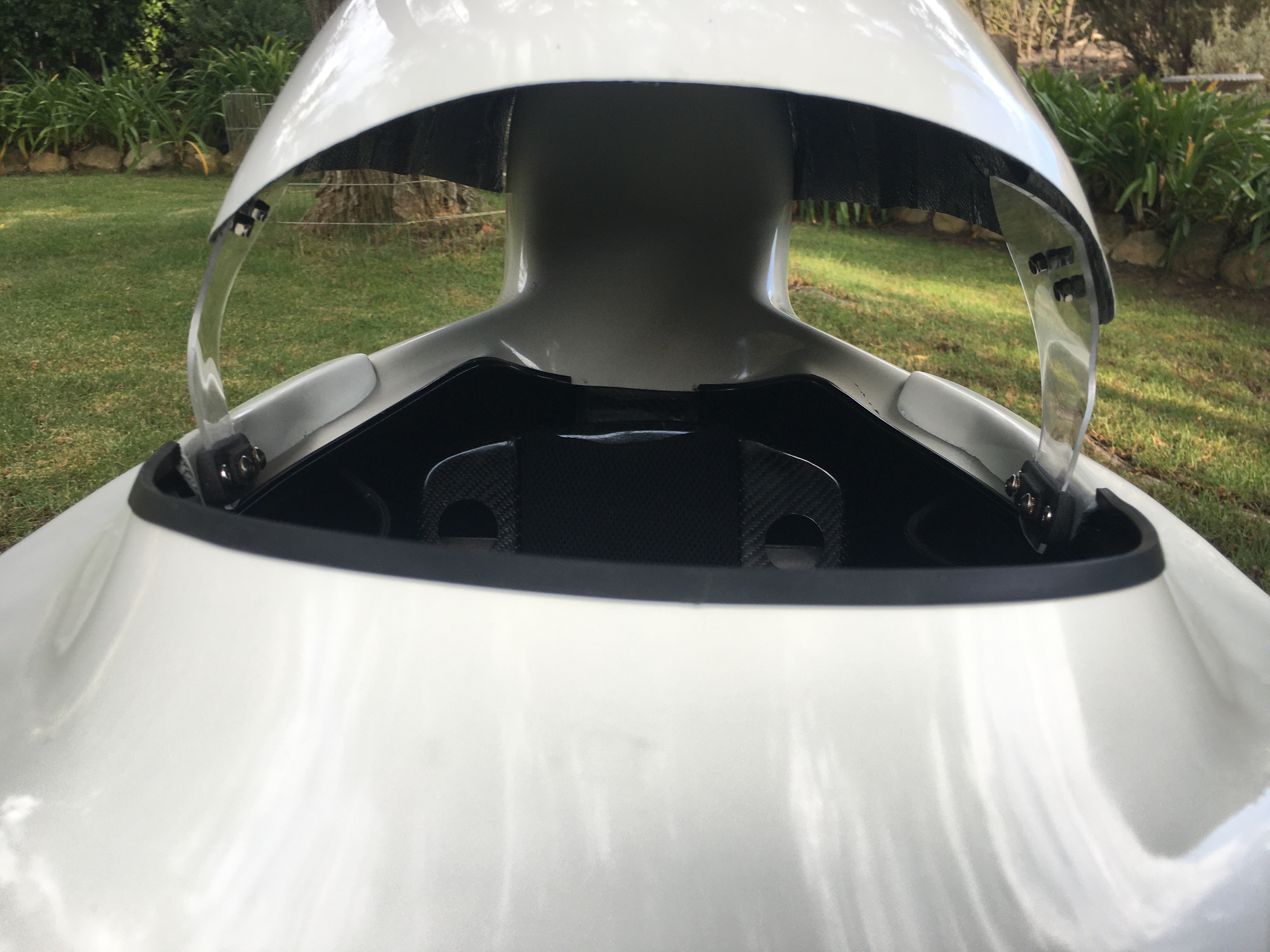
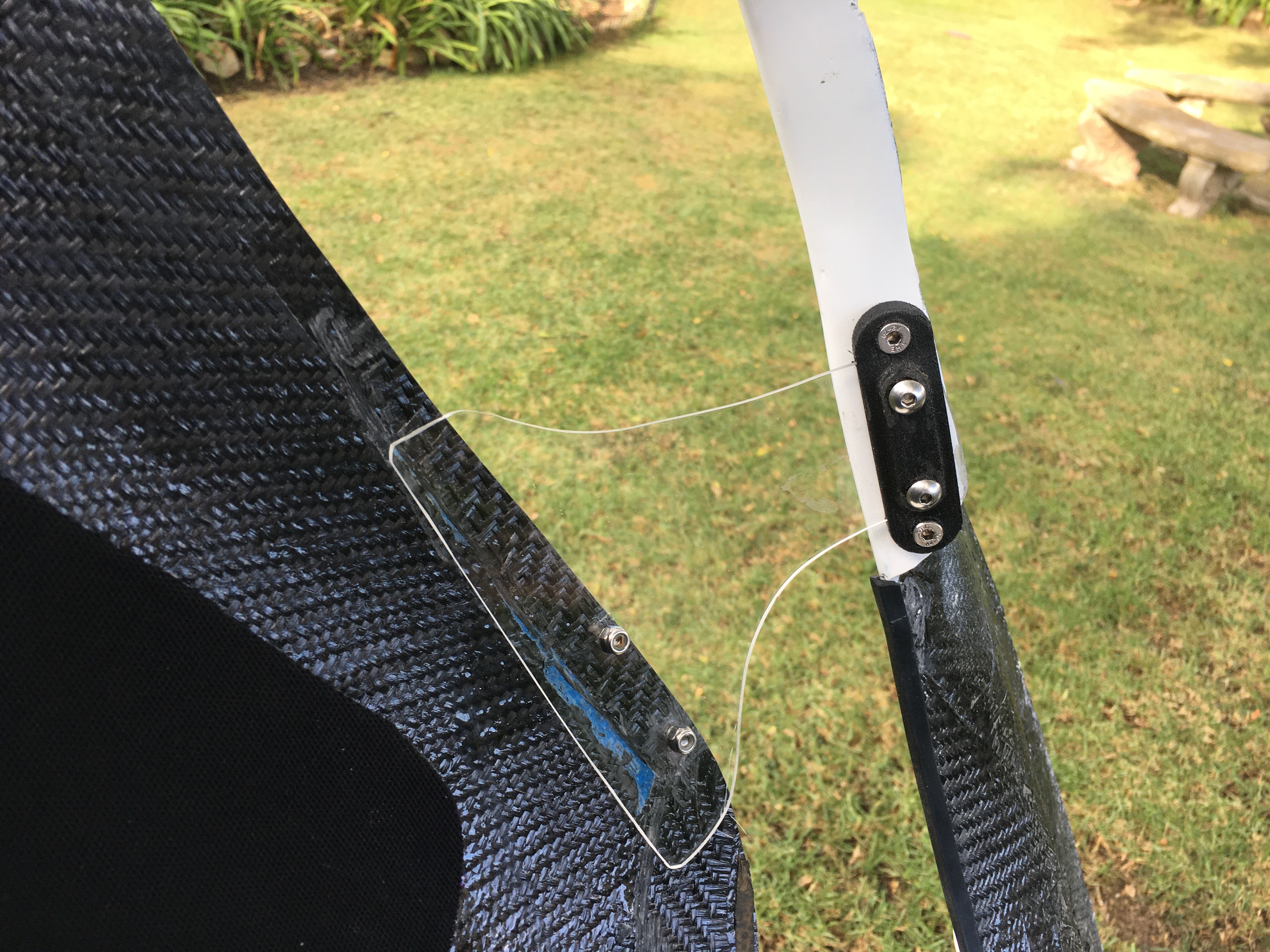
Besides bonding the new boom onto the existing pedestal and crossmember, it seemed like a good idea to add some reinforcements. At the cockpit end of the boom, I made a carbon fiber vertical support going from the top of the boom to the reinforcement rib on the underside of the cowling. For this piece, I shaped a foam prototype, body worked it then made a mold of the prototype. I purposely built this support with the opening of the boom uncovered. This would allow me future access for repairs and also the potential to use the boom as a cooling duct.

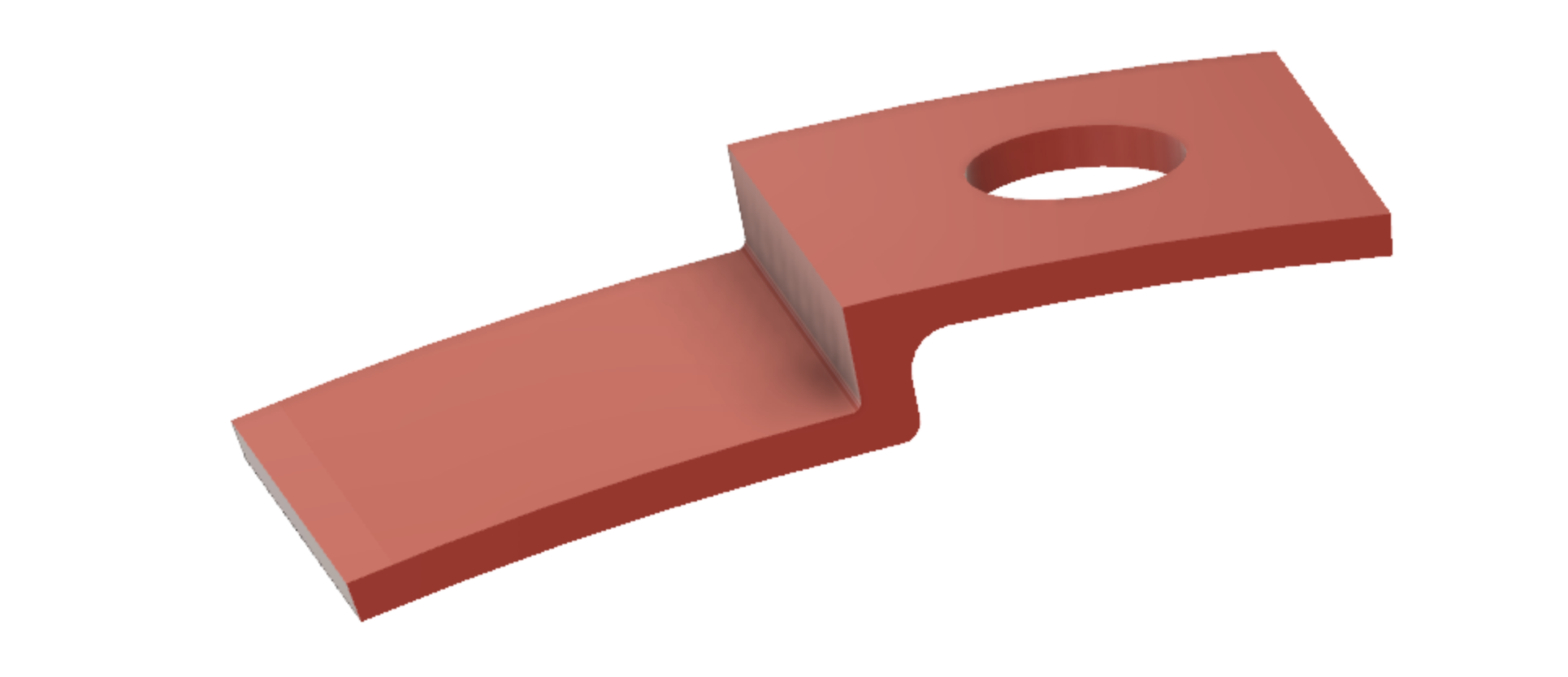
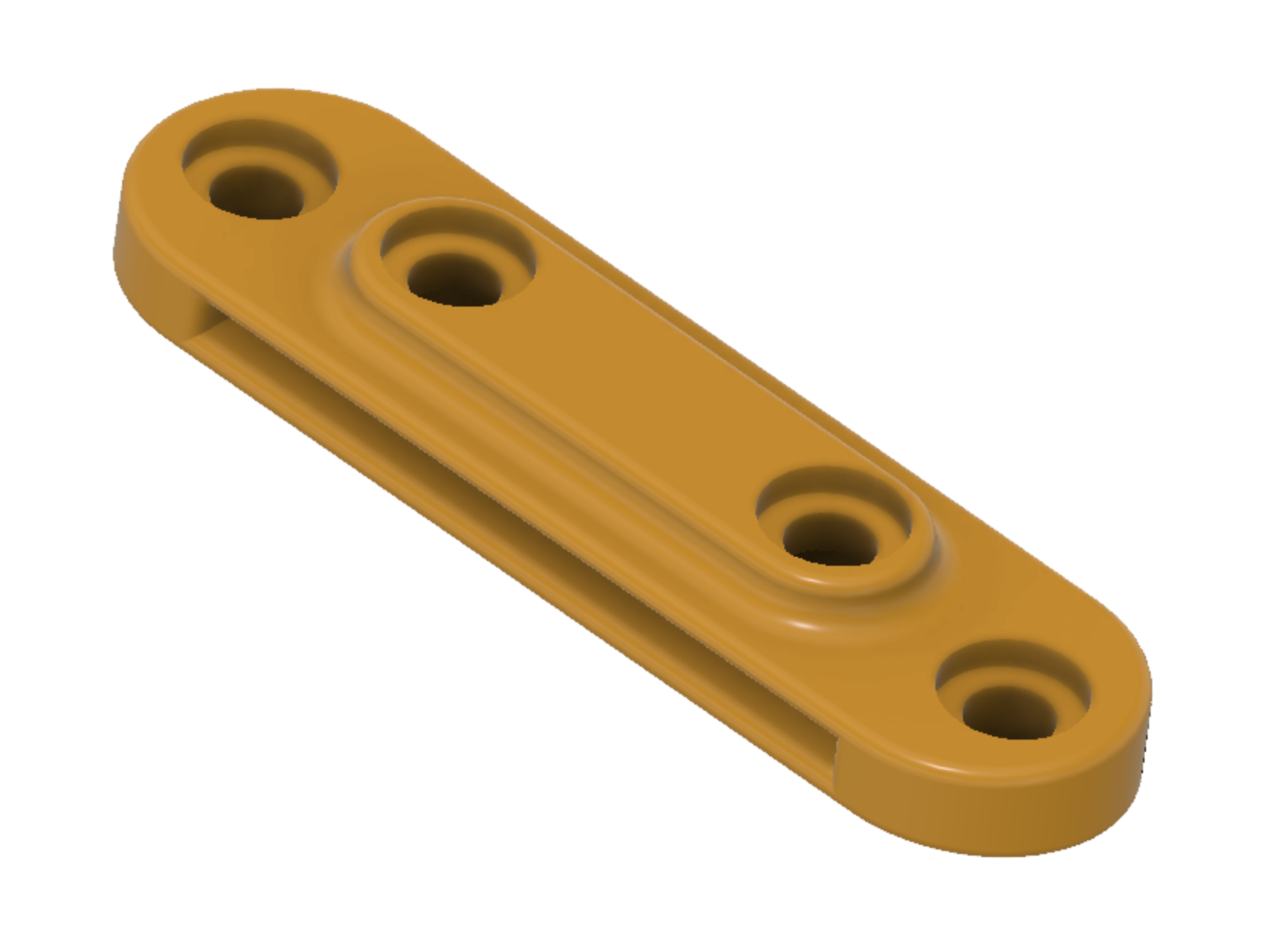
At the front attachment, I used a technique of molding compressed, chopped carbon fiber called Forged Carbon fiber to make left and right support structures to reinforce the boom connection to the front cross member. This technique involved modeling the structure in Fusion 360. In Fusion 360, I then built a solid shape that enclosed the structure. Combining and subtracting the structure with the solid shape left a negative impression or mold of the desired part. I could then easily have Fusion 360 generate the mirror image of that mold. From there, I 3D printed both (L & R) molds. The forged carbon fiber parts were then made in those molds and bonded in place using structural epoxy adhesive.

Using a larger cross section tube for the boom introduced a couple of other minor considerations. The location of the bottom bracket spindle had to remain at the same relative height as the old spindle in order to prevent my toes and heels from scraping the inside of the nose. Fortunately, the new bottom bracket sled positioned the spindle closer to the boom surface than the old plastic sled by about 4mm. This reduced the 10mm offset of the new taller boom. I had to remove only about 6mm of material from the pedestal and the cross member in order for the new bottom bracket spindle to keep the correct vertical position.

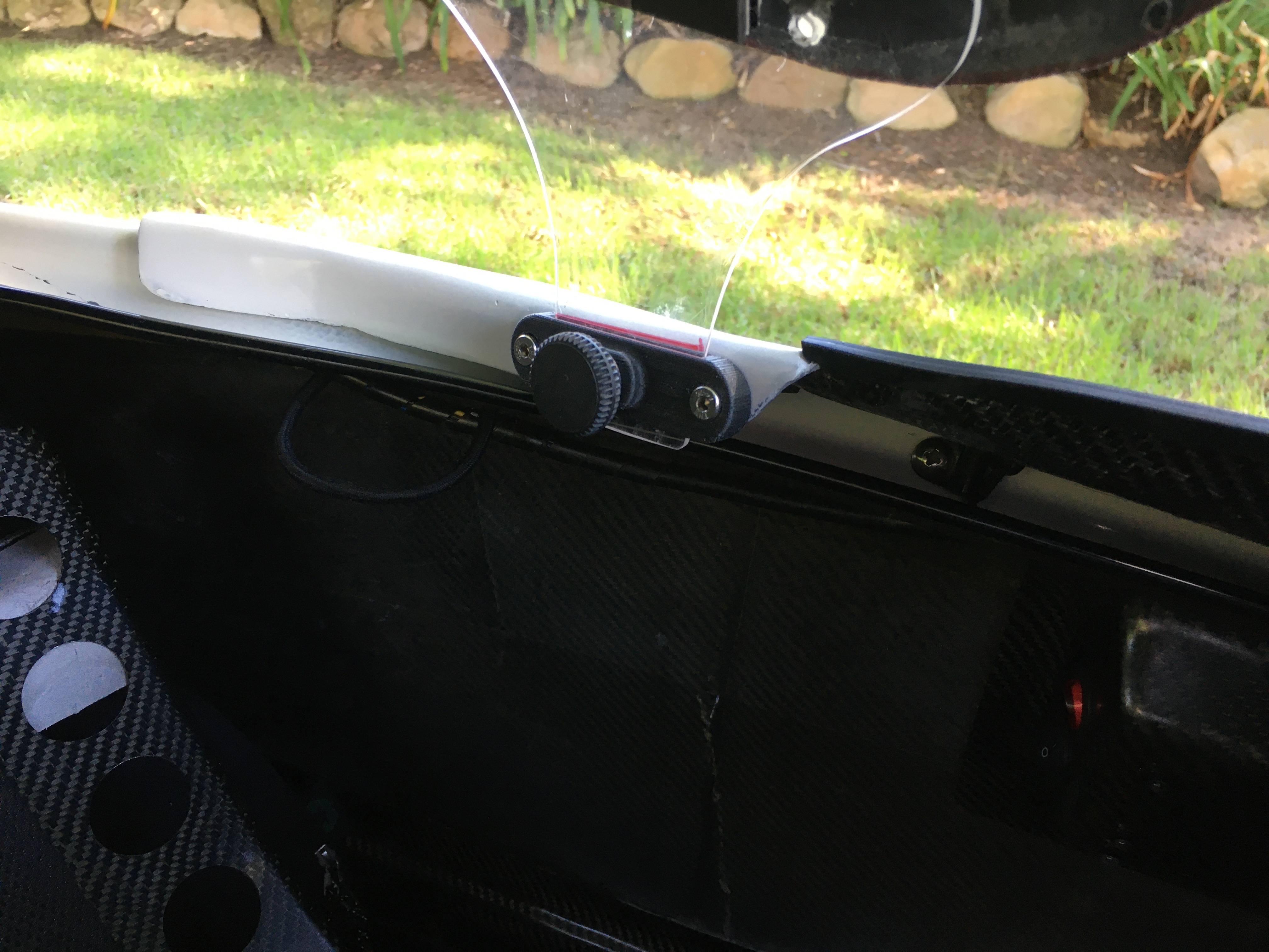
The headlights were mounted on a bracket on top of the old boom. By correctly positioning the new boom vertically, I was able to mount the lights on top of the boom, maintaining the correct alignment with the body opening for the headlights.

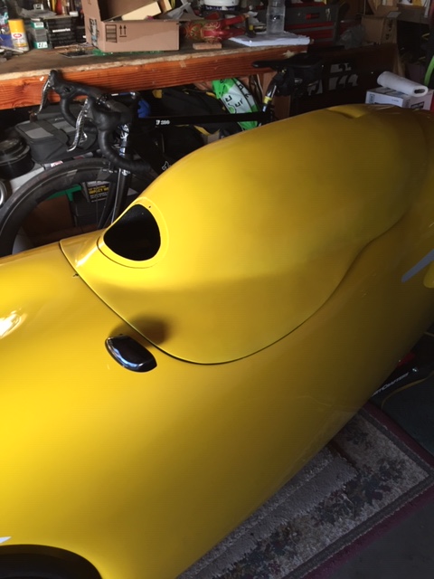
One future enhancement that I’m considering is adding a fresh air opening in the nose. The boom is open at both ends so any air passing through would flow right to the rider. As it stands now the only opening in the nose is occupied by the 2 headlights that sit on top of the boom.

Was it worth the effort? It was a lot of work, but I’d say that it was absolutely worth it. Adding the new access hatch and larger boom have really enhanced the Canadian Milan SL. The boom is rock solid. Adjusting the bottom bracket, the front derailleur and changing chainrings up front no longer require major gymnastics with the addition of the access hatch.

Trice Special -> Trice Cheater

My mix and match Trice, the Trice Special, has been transformed into the Trice Cheater. About 6 months ago, I installed a Bafang motor system on my wife’s Trice Special. It turns out that she just never got around to riding it. Since I needed an e-trike to ease back into riding after back surgery, I decided to take the Special back and configure it for me.

Since I feel a bit guilty riding with e-assist, I renamed the trike the “Cheater”. The Bafang system is functional but kind of funky. I replaced the stamped steel chain ring with a nicer and larger CNC aluminum chain ring. The motor and crank arms are offset to the left of center so I installed some Lekkie Buzz Bars (offset crank arms). The motor is secured to the bottom bracket by a single nut and a screw on cap over that nut. I replaced those pieces with a the much nicer and more secure Lekkie Onenut. The only thing that prevents the motor from rotating upward during acceleration was the friction between the bottom bracket and that single nut. I installed the Utah Trikes torque arm which does a better job of keeping the motor in position. And finally there was no accommodation for mounting the battery on a trike. Terracycle makes a very nice aluminum mount designed specifically for the Trice frame.

Peter Borenstadt Fastest in Mens Multitrack at Battle Mountain 2023

56.91 mph ( > 91 km/hr )

Good news! Peter Borenstadt hauling ass at the 2023 Battle Mountain Human Powered Speed Challenge in his DF velomobile sporting some of our new custom aero parts – the wrap-under tail extension, reduced frontal area hood and nose cap.

Check out some of the parts we made for Peter’s DF for this years Battle Mountain…

DF Updates for Battle Mountain…

DF 141 Gets a Paint Job

The DF was getting a bit beat up from using it as a workbench to develop body parts. Also the adhesive from the tape used to mount the body parts was attacking the paint job. So, it was time to freshen it up. I played with a bunch of different color combinations in Pixelmator Pro. Here are some examples (no. 1 is the my original paint scheme):

I really like the Porsche factory color called Miami Blue. It’s similar to the stock blue that all velomobile manufacturers use (RAL 5015 Sky Blue), but it’s a bit brighter with a little more turquoise tint. When I saw a photo of a Milan in solid Miami Blue (the small image in the corner), I decided to copy that look. Here’s the Pixelmator Pro image of the Miami Blue DF.

Below are some photos of the DF post paint job. I like the combination of orange with this color of blue so I sourced some reflective orange vinyl and used my vinyl cutter to produce the factory shaped stickers in orange. I positioned the front stickers a little differently than ICB does at the factory. Mine are more level with the ground and further back from the nose. In the first photo, you can see how the new color compares with the old factory blue panel.

Painting the DF took about 3 weeks. A day or two of that time was spent in the actual disassembly and reassembly of the DF. But most of that time was spent allowing various coats of primer, paint and clear coat to dry properly before moving on to the next steps.

There were a lot of pieces that had to be prepped, painted, clear coated, wet sanded and polished including 2 hoods and 2 front covers not shown.

Here’s my high tech paint shop.

Milan SL at Cars and Coffee

Every Sunday morning, car fans from around the Santa Barbara area gather at Manning Park in Montecito for a 2 hour informal car show and BS fest called Cars and Coffee. I’ll admit that I’m still a car guy so I drop into the C&C most weeks. Yesterday, I decided to show one of my exotic cars – my Milan SL. I pulled my ratty Odyssey mini-van into one of the outer parking spots (the inner spaces are informally reserved for the exotics and high dollar cars). A few people took notice when I opened the back door, slid the Milan out and set it on the ground.

After answering a few of the usual questions, I hopped in and did a slow lap around the lot back to my car. When I climbed out, I was surprised to see that quite a few onlookers had left the exotic cars and followed me to have a look at my “No Motor” velomobile. I explained the design and some of the features of the Milan to these observers in car terms such as “monocoque” and “Macpherson Strut”. I heard a lot of “thanks for sharing this” and “this is so cool”. I’m sure there were no converts among them, but I think they developed an appreciation of my “bicycle for car guys”. It was fun.

Battle Mountain Updates for Peter Borenstadt

I’ve made some parts for Peter Borenstadt’s DF for his Battle Mountain runs in the past. This year we’re going to try a few new tweaks. First, I’ve made a slimmed down version of my DF race hood by reducing the top and sides of the current version. Here are some photos of the effort.

Peter also wanted to improve the air flow through the cockpit, hoping that it may reduce overall drag of the DF and perhaps reduce CO2 levels in the cockpit. One way of doing this is to drill several large holes in the trailing edge of the DF. However that’s difficult with the tail extension coming to a point. He suggested adding a vent to the derailleur cover to see if that makes a difference. Here’s what I came up with:

It seems to allow air flow through the opening without messing up the air flow of the surrounding tail surface. We still won’t know if it actually makes a difference until Peter has a chance to test it.

Update:

Even though the tuft test looked OK, in practice it seems that under some conditions, the flow reverses into the vent bringing road dust and grime with it. The panel is now on the back burner.

Probably the last piece that I’ll make is a new tail extension. The goal here is to improve on the existing tail extension by adding a piece to fair in the trailing edge of the rear tire. In the past, we tried a rear wheel fairing but that seemed to unsettle the DF’s rear end at high speed. Rather than build a new rear wheel fairing, he thought that it might be worth trying to extend the tail extension lower and forward to at least fair the trailing edge of the rear tire. While we are at it, we thought we’d remove the concave curved area on the top of the tail fairing and shape it to continue the DF’s rear hump.

Here’s a bad Photoshop rendering of the proposed changes to the tail fairing.

Update:

Here’s the red plug (prototype) used to make the mold of the tail extension. The first part has been made but not delivered to Peter yet. Performance testing is still to be done.

Airliner Update – Airliner Cancelled

I’ve been running a tubeless rear wheel with Airliner on both velomobiles for a couple of months now. They’ve been working well but I haven’t had any punctures during that period of time. I’ve heard stories of Airliners shriveling up and of the liquid sealant drying up. I think that these cases might have been due to the use of a non-Vittoria sealant. I decided that it would be a good time to open up a tire to check on the state of the Airliner and sealant. I removed the Milan rear wheel and opened one side of the tire to have a look. The short story is that the Vittoria sealant was still in the liquid state and well distributed. The Airliner looked exactly the same as when I installed it. That’s the good news.

The bad news is how difficult it was to do the inspection. I was able to break the bead away from the rim pretty easily using the Vittoria tool. But stretching one side of the tire over the rim wall to remove the Airliner took a couple of hours of breaking tire levers and swearing. Then reinstalling the Airliner and tire took a couple more hours … and I was never able to stretch the tire back onto the rim.

Since I wasn’t able to re-install the tire with Airliner, I had to come up with a plan for a rear wheel setup on the Milan. After struggling for hours with the tubeless tire – Airliner set up in my garage with access to all of my tools, I realized that it would be impossible to deal with it on the road. The Airliner isn’t the solution that I had hoped it would be. I could just replace the Airliner wheel with my original non-tubeless rear wheel. However, I decided to install the tubeless tire without the Airliner. I was surprised at how easy it was install the tire without the Airliner.

I realize that I’m giving up the safety benefits of the Airliner with this decision. However, I do think that the use of a standard tubeless tire / rim may be safer than my previous non-tubeless setup. I believe that a tubeless tire is more likely to stay attached to the rim when a flat occurs.

Vittoria Airliner – Velomobile Rollover Prevention?

One of the things velomobile riders fear most is a high speed roll over. Anything that causes the rear tire to lose grip at high speed can lead to a roll over. Riding with the rear tire on a roadside rumble strip can induce a roll over. Here’s an example of that:

Another common cause of a velomobile roll over is a rear tire flat. It seems to be even worse if the tire breaks free of the rim. Vittoria has come out with an interesting product, called the Airliner, that could bring a new level of safety to the rear flat situation. The Airliner is a light weight foam ring inserted into a tubeless tire/rim that compresses to a fraction of its volume when the tire is inflated, then expands to fill the tire if the air escapes the tire. Under these circumstances, the tire behaves as though it has a pressure of 25-30 psi. This should be enough to keep the tire on the rim. The fact that it is compresses out of the way when the tire is inflated makes the tire behave like a normal tubeless tire. You can read about it here… or watch this video.

Tubeless Technology

I decided to give Airliner a try. This is my first time working with tubeless technology. The tubeless wheel consists of a tire with a special bead that mates to a rim with a compatible tubeless profile. The rim is taped with a special tape. Also a special valve stem is required. After all of that is put together a small volume of a sealant liquid is introduced into the air space of the tire. Once the tire is seated on the rim, the bead locks into the rim’s hook profile, making it very difficult to separate the tire from the rim. There’s a good overview of tubeless technology here…

Rear Wheel Build No. 1

Neither of my velomobiles had a rear wheel with the required tubeless rim so I set out to build one. I found a source for a new DT Swiss 559 tubeless rim on eBay. I had a conventional rear hub and a wide selection of spokes in the drawer. Since the Milan accepts a conventional rear hub, it was chosen to be the test mule.

This first wheel didn’t work out as I had hoped. I built the wheel with the DT Swiss tubeless rim and mounted the Schwalbe Pro One tubeless tire containing the Airliner. Surprisingly, the Airliner Road version fit the 559 tire without cutting it even though it’s sized for a 700c wheel. I applied soapy water to the bead before inflating it with an air compressor. The tire seated on the rim and held air just fine. However, when I then deflated the tire, simulating a flat, the tire’s bead separated from the rim, making it possible for the tire to escape the rim. This combination of tubeless tire and rim were not going to work.

Rear Wheel Build No. 2

Next I bought a 559 Alex tubeless rim on line at Universal Cycles. I disassembled the wheel with the DT Swiss rim and re-assembled it using the Alex rim. I mounted the same tubeless tire with the Airliner and soapy water and filled it using the compressor. The tire’s bead seated perfectly on the rim. This time the tire remained firmly locked to the rim when I deflated the tire. So I now felt confident enough to inject about 30cc of liquid Vittoria sealant through the valve stem with the valve core removed.

Testing the Airliner at zero pressure

I inflated the tire to 85 psi then mounted the wheel in the Milan and set off for a ride. At this pressure, the Milan’s handling felt normal. I stopped near a bike path and deflated the tire. The Airliner expanded within the tire to give it enough shape that the rim didn’t contact the pavement. So far so good. I set off for a ride with zero pressure. Vittoria says that the Airliner alone should provide the equivalent of 25-30 psi of air pressure. That’s what it felt like to me. The rear end of the Milan felt a bit squishy of course but it was manageable. I rode for about a mile on a combination of smooth bike path and rough pavement on an adjacent road. I kept the speed below 15 mph. I took some turns at a reduced but reasonable speed just to complete the test. The tire remained locked to the rim as I had hoped. I called that a big win.

Testing the Airliner’s Effect on Performance

There’s a hill near my house that I have used to do coast down tests to measure maximum speed with an onboard wired cycle computer. I do these tests to compare the effects of modifications and adjustments that I make to the velomobiles. I was curious to see if the presence of the Airliner would adversely effect the maximum speed of the Milan. I did a couple of runs with the original Pro One/latex tube wheel that I normally use and a couple of runs with the Pro One/Airliner wheel. All of the runs showed the same maximum speed within a few tenths of a mile per hour.

Conclusion

The Airliner performed as advertised once I got the combination of rim and tire correct. The fact that I was able to ride a mile on zero air pressure in the rear tire without the tire leaving the rim convinced me that the Airliner will work in the event of a normal flat. I’m also convinced that there is no performance penalty to pay running the Airliner.

On the negative side… I wasn’t able to simulate a blowout so I don’t know how well the Airliner will perform in that case. Another potential concern is that I will have a difficult, almost impossible, task of removing the tire from the rim to repair a flat or replace a damaged tire while on the road.

I’m convinced that the extra precaution against a roll over makes the use of the Airliner worth while. I will leave it on the Milan and build a tubeless rear wheel for the DF to run an airliner on it.

Links

Milan Shade Cap – Splittable and Stowable

I’m still having fun building parts for the Milan SL. My last piece was the head out lid and shade cap. After building these pieces, I realized that I should be able to stow the cap inside the Milan. The single piece cap assembled with its pillars doesn’t fit in the available space in the Milan. Stealing some ideas from Wim Schermer’s splittable Quest hood, I came up with a quick way to remove the pillars and split the cap into 2 pieces without tools.

Here is the unpainted hood – split down the middle. At this stage, it still had the pillars mounted with screws.

One of the problems I had to solve was to come up with a quick way to join the halves without using tools. I settled on using 3M Dual Lock. The idea was to fabricate a flange or lip on the underside of one half of the cap, for the full length of the split. The lip would have enough depth to allow 2 thicknesses of Dual Lock. Here’s a cross section to show what I mean.

Laying up the flange didn’t sound like a lot of fun so I came up with an easier but less optimal way to accomplish the same thing by 3D printing something similar. Rather that printing a flange for the whole length of the split and trying to get the curvature right. I decided to print some 1″ long sections of flange, using carbon fiber/PETG filament, and epoxy them on one half of the cap along the split. Here’s the design of the piece. Also shown is the underside of the cap.

The next item to address was getting rid of the screws holding the pillars to the cap. I ended up using a slightly re-designed flange piece to attach the pillars using Dual Lock. Lastly, I wanted to get rid or the 2 allen screws on the clamps holding the lower pillars to the lid. I redesigned the clamp to use only a single M6 thumb screw. Here are some photos…

There’s a problem with the approach I’ve taken though. The split is not entirely sealed against the elements since there lip doesn’t run the whole length of the cap. If, over time, I find that this splittable cap is worth keeping, I’ll replace the one inch flange pieces with a full length carbon fiber flange.

Removable Shade Cap for the Milan

After finishing the head out lid for the Milan SL, I thought about those sunny days that I need the added air flow of the lid, but also want some shade. I looked back at the shade cap that I made for my WAW. It worked well and I liked the way that it looked. So I decided that I should make a similar removable shade cap to use with the head out lid of the Milan.

Here’s my WAW shade cap from a few years ago. The WAW has some nice clamps installed on the inside of the lid near the cockpit edge. These were great for mounting the clear plexiglas posts shown below. It only took a few seconds to loosen the clamps to remove the cap.

WAW Shade Cap

I already had a scrap piece of a hood from my Milan’s one piece hood mold. I just needed to come up with the plexiglas posts and some clamps similar to those used in the WAW.

Here is the Milan shade cap. Notice in the head on view below, how much open space there is for air to pass through.

Here’s the clamp that I designed to mount the clear plexiglass posts. I printed them with carbon fiber / nylon filament and embedded metal M5 threaded inserts.

By the way… I’m aware that the Milan’s aerodynamics are most likely compromised with this cap, but its only purpose to keep me comfortable on warm days.