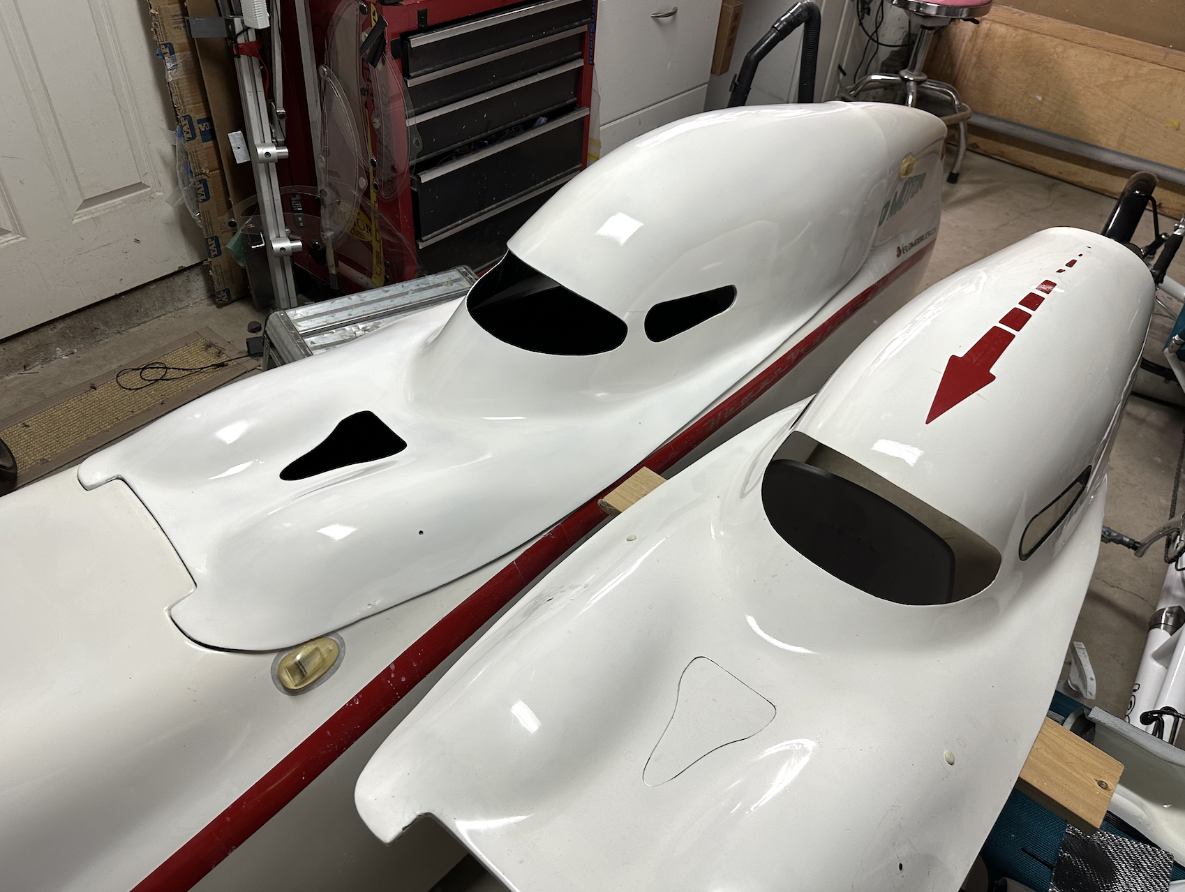
I’ve been attempting to improve the air flow in the Bulk Mk1. I’ve learned a few things that confirm that there are some design limitations in the Bulk Mk1 to overcome.
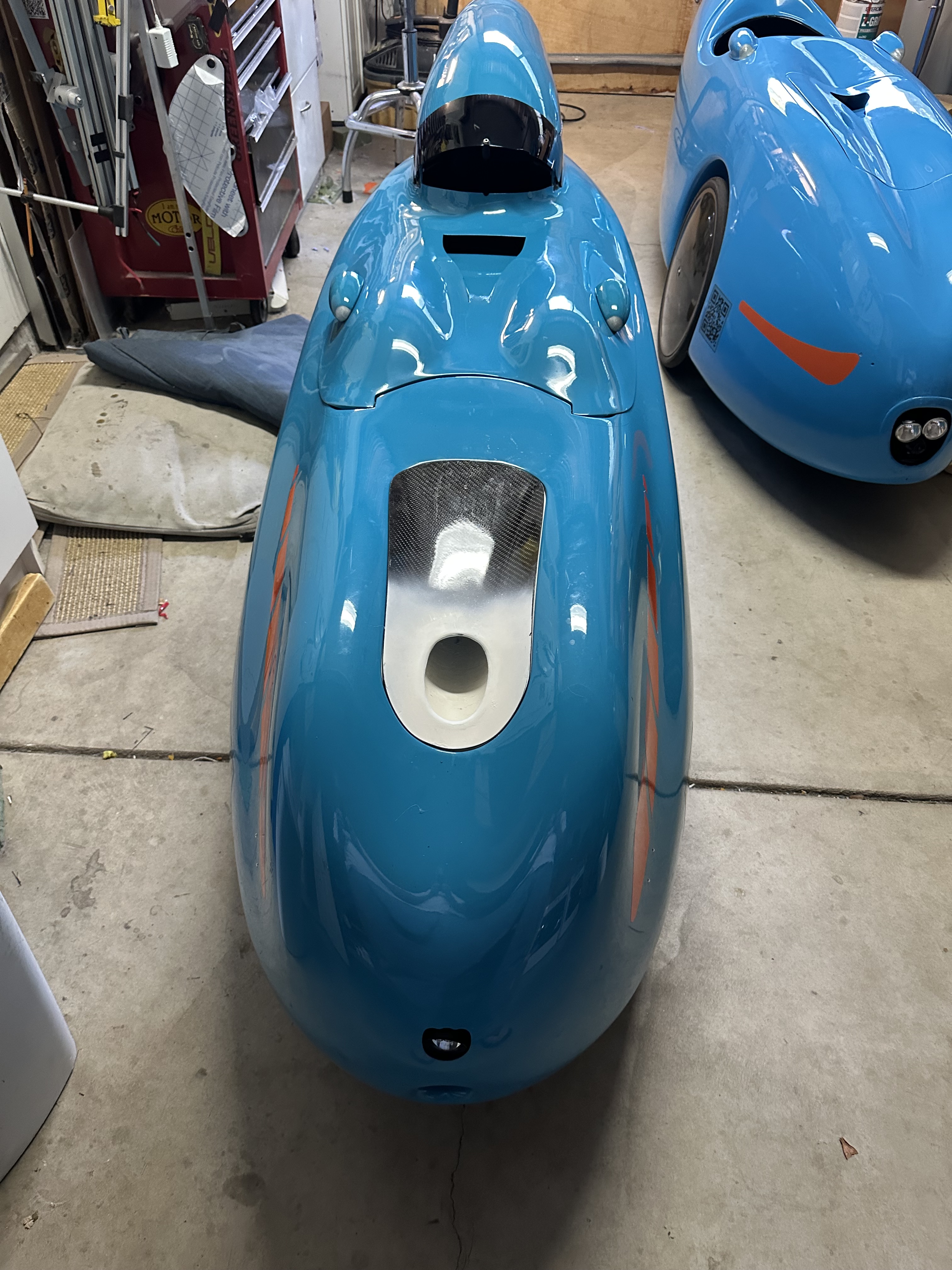
In the stock configuration, only the holes in the tail of the Bulk provide an air outlet. However, the pathway to those holes is very restricted. On the right side, there is a solid carbon fiber panel below the tray which blocks off the air flow on that side. On the left side, the gap between the wheel housing and the concave body is very small which restricts the air flow on that side. With these restrictions, the cockpit can easily become pressurized which limits the volume and velocity of incoming air flow. I’ve made a series of changes. Here is some crude tests that I performed to see what worked and what didn’t.
Current Modifications
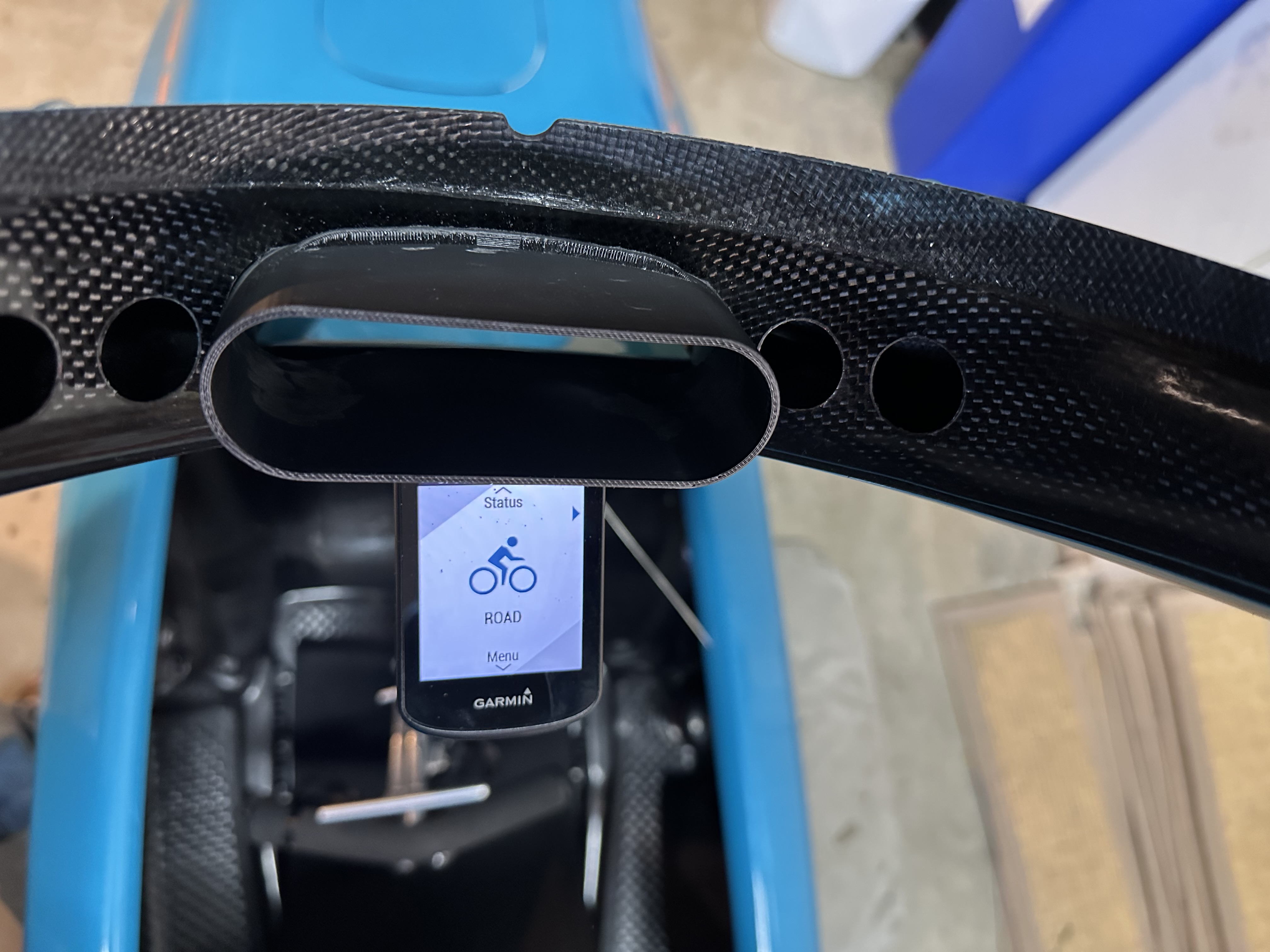
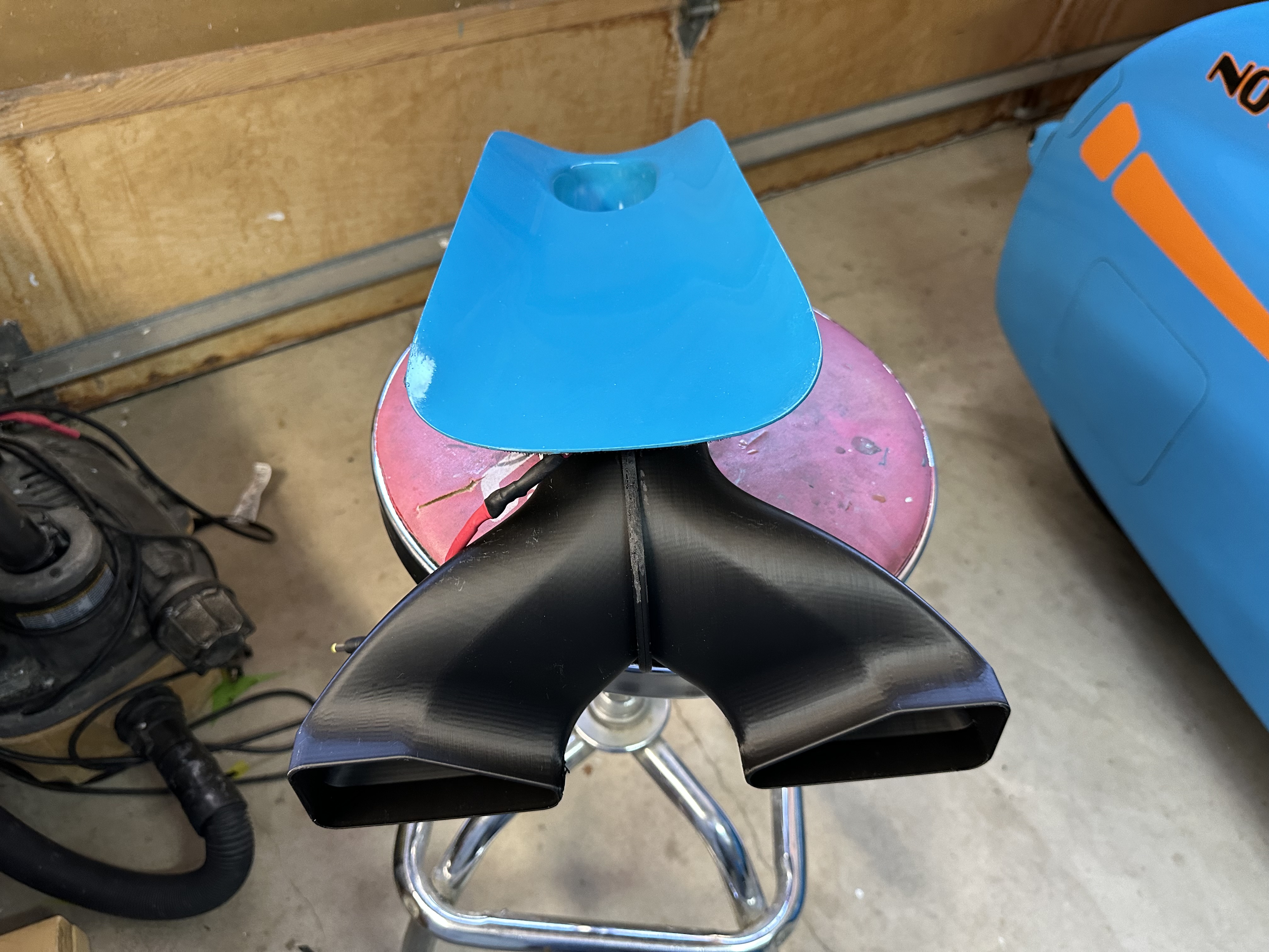
- I’ve improved the NACA duct by installing the vertical walls of the duct, enlarging the outlet slot and adding ducting from the NACA duct exit to the slot on the interior panel.

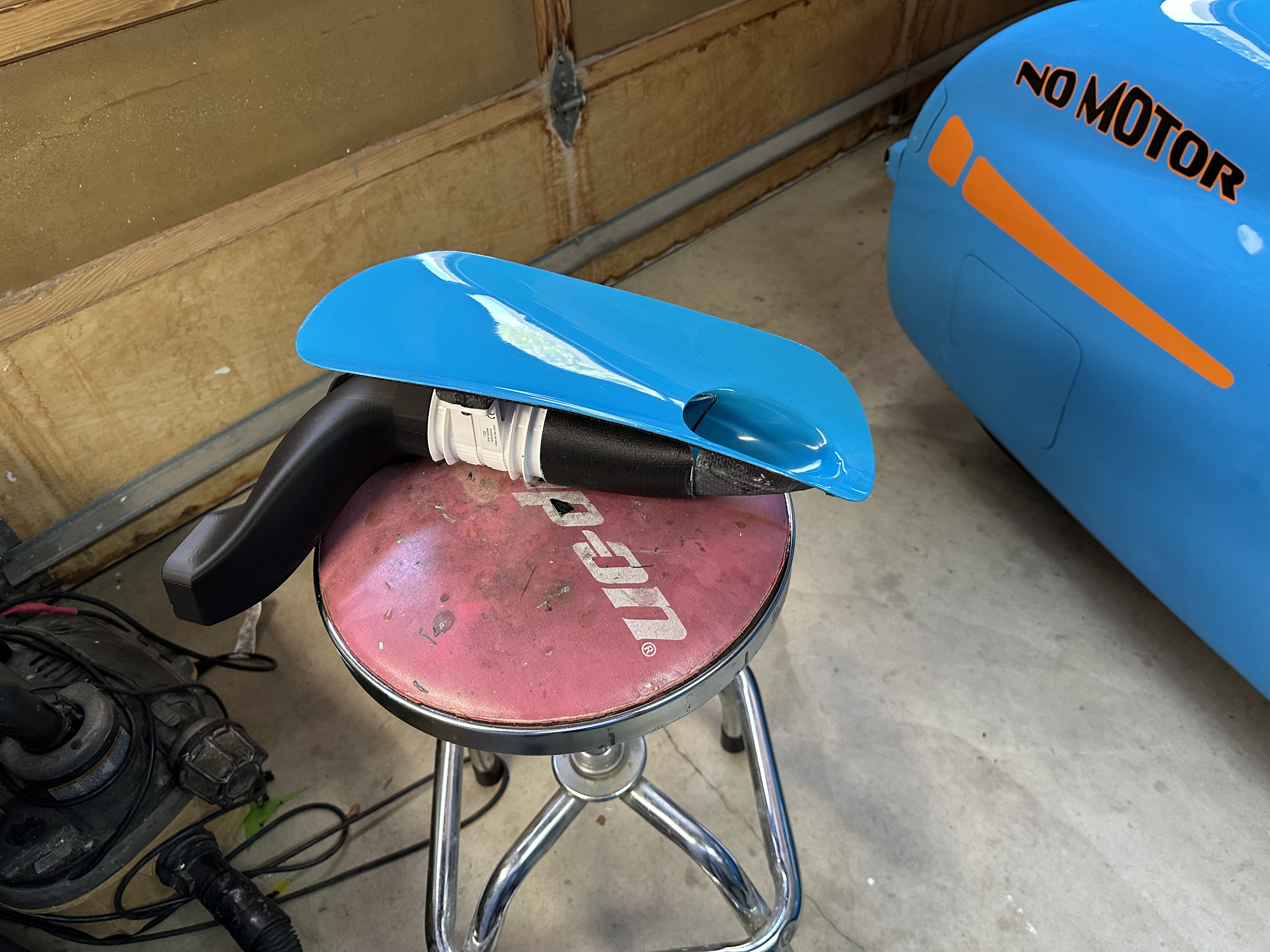
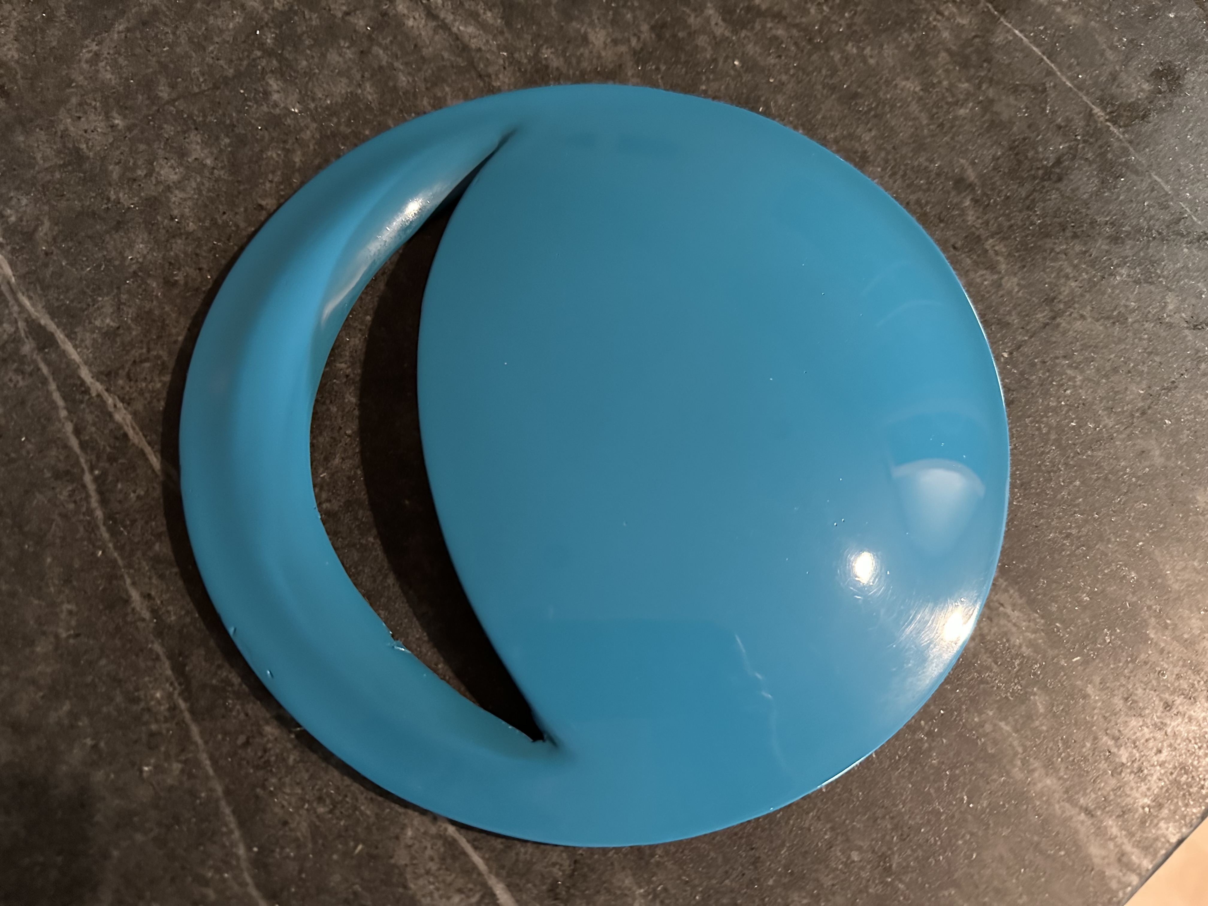
- Built a front access cover with a vent – no fan

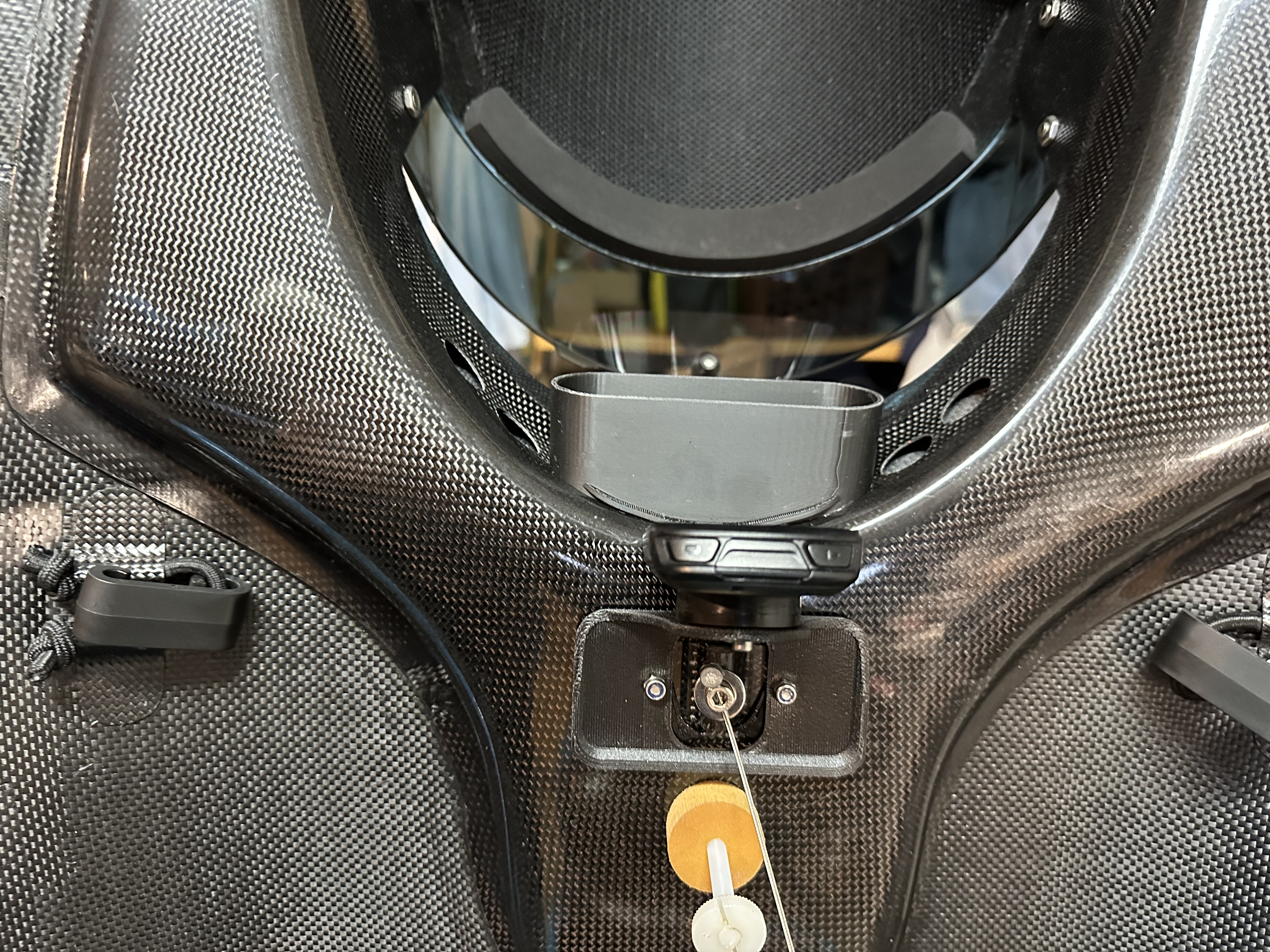
- Built a front access panel with an inline fan and ducting
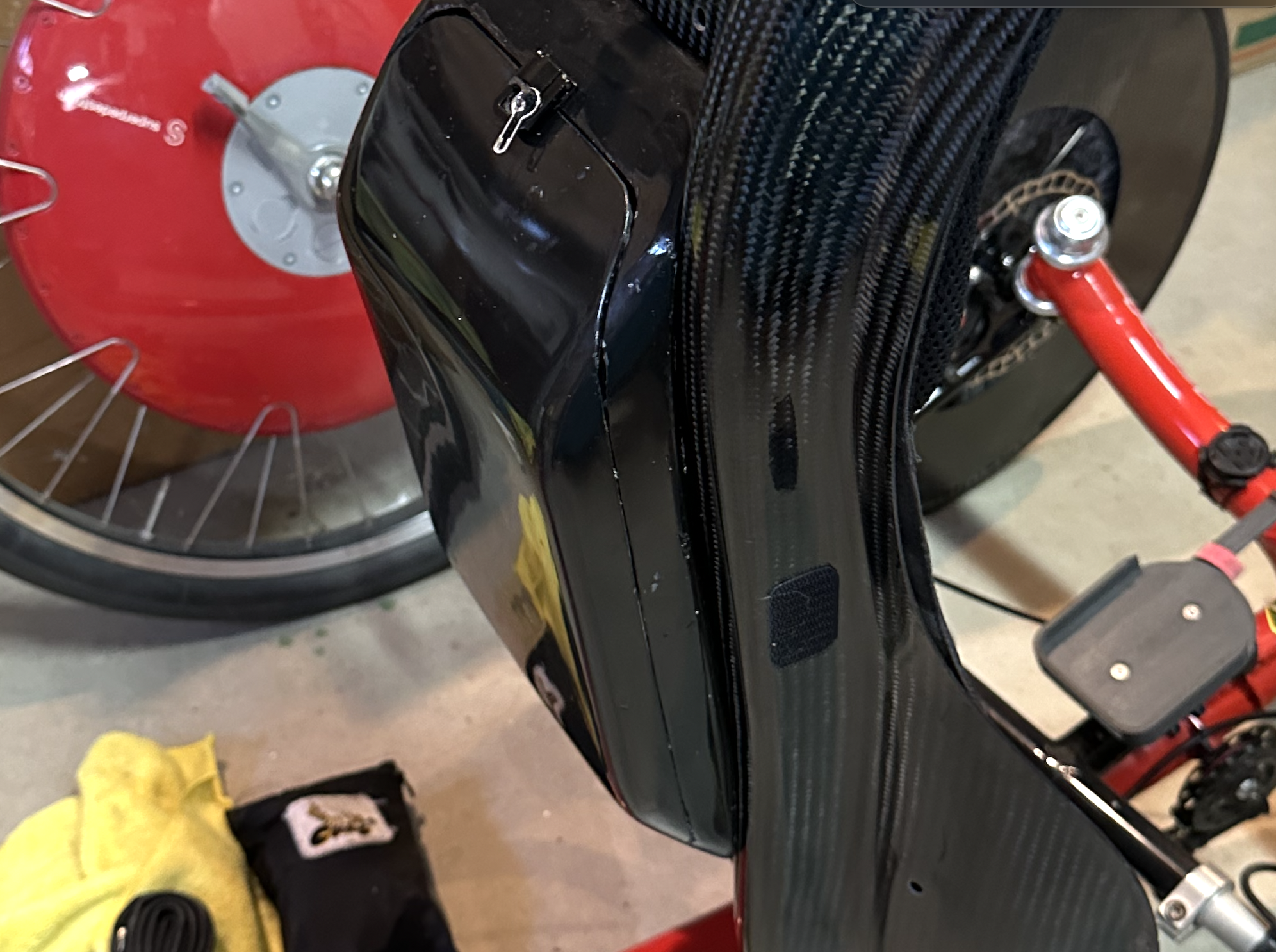
- Replaced the solid carbon fiber panel (below the tray) with mesh material.


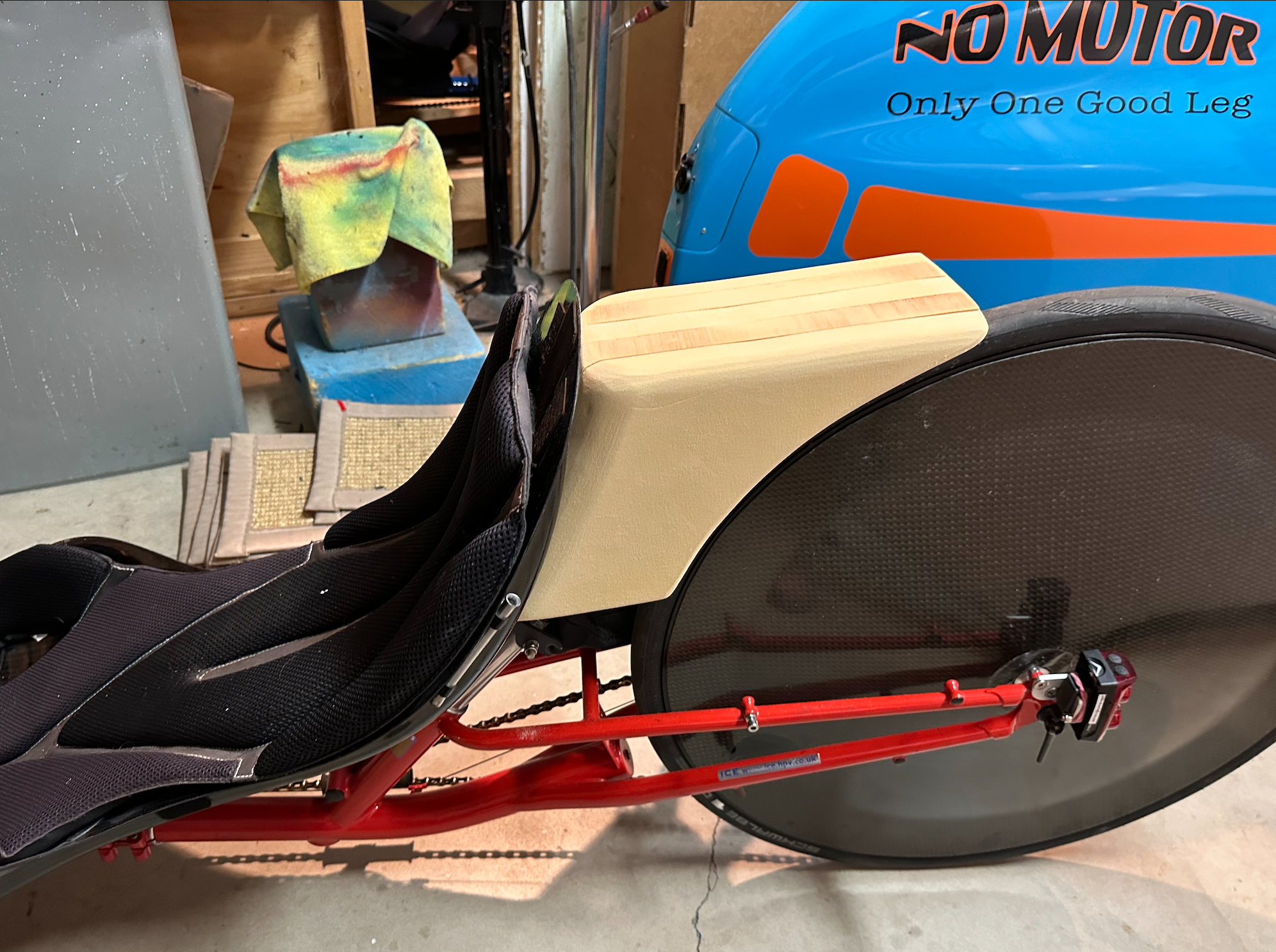
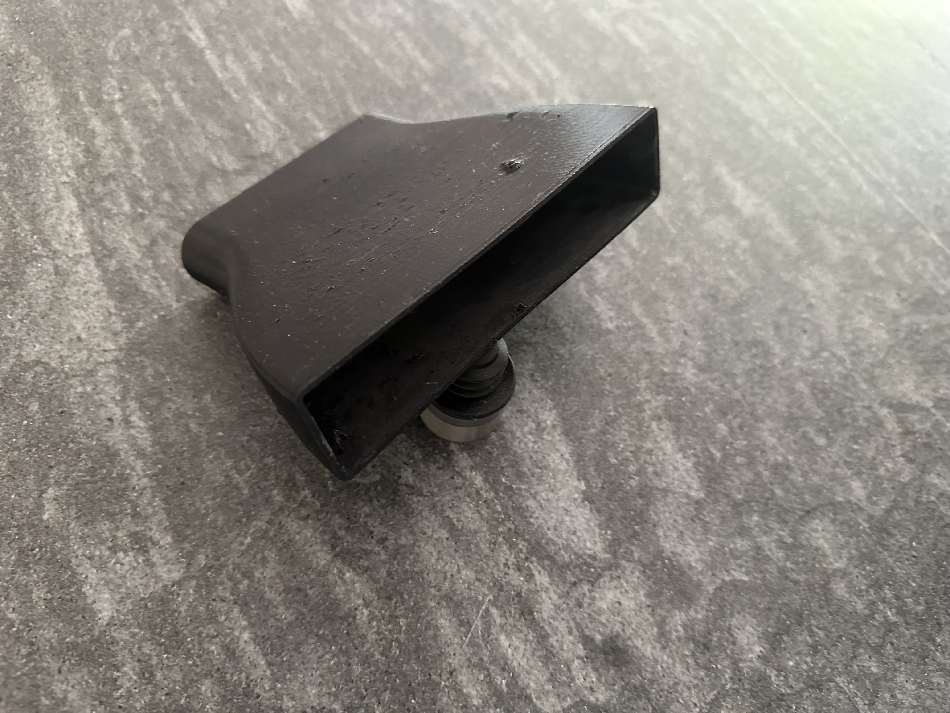
- Built a derailleur cover with an outlet vent.
- Added small handles to the side windows to manually open and close them.

How I tested:
- I only tested wind speed at the NACA duct outlet into the cockpit. I attached a small wind meter in front of the NACA duct cockpit opening. For each series of tests, I established a baseline configuration, captured the windspeed for that baseline. Then I ran the individual tests, changing only one thing per test and noting the windspeed. The actual windspeed number in mph isn’t critical – only the relative amount of change vs the baseline value, positive or negative mattered.

- I maintained 20mph speed on a flat, straight bike path for each of the tests, noting the windspeed measurement for each test.
- No consideration was given to the aerodynamic costs of any of these changes.
Baseline Configuration
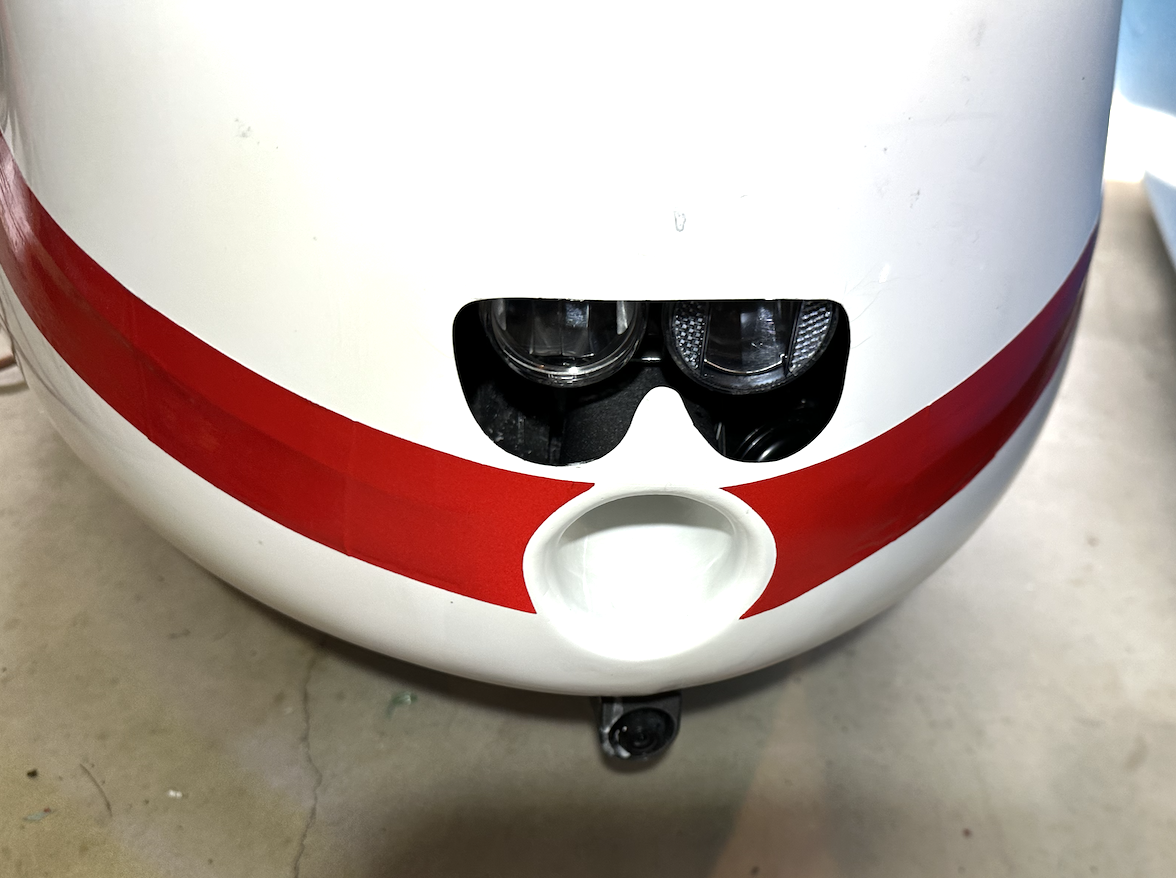
- Race hood in place
- Visor down
- Modified NACA duct fully open
- Center vertical strut air opening fully open
- Side windows in place
- Stock front access cover (no vent, no fan)
- Solid carbon fiber panel below tray
- Travel at 20mph on straight, flat bike path for approximately 1/8 mile out and 1/8 mile back
Test Series A: The Baseline meter reading : (actual speed isn’t important – only the delta)
- Visor fully open
- Hood manually pushed up forming an approximate gap of 1″
- Left side window manually pushed out forming an approximate gap of 1″
- Both side windows pushed out
- No side windows
- Vented derailleur cover with mesh
- Vented derailleur cover with no mesh, no panel
Test Series B: Repeat the tests with same baseline but access cover with vent but no fan installed
- Visor fully open
- Hood manually pushed up forming an approximate gap of 1″ – meter reading
- Left side window manually pushed out forming an approximate gap of 1″
- Both side windows pushed out
- No side windows
- Vented derailleur cover with mesh
- Vented derailleur cover with no mesh, no panel
Test Series C: Repeat the tests with same baseline but access cover with fan at full speed
- Fan at full blast
- Visor fully open
- Hood manually pushed up forming an approximate gap of 1″ – meter reading
- Left side window manually pushed out forming an approximate gap of 1″
- Both side windows pushed out
- No side windows
- Vented derailleur cover with mesh
- Vented derailleur cover with no mesh, no panel
Discussion:
Based on the tests above, there were some observations that were consistent across all 3 scenarios.
- The NACA duct provides decent air flow when the side windows and visor are closed. It improves with partially opened side windows. The more they’re opened, the more improvement was seen up to a point.
- The NACA duct air flow also improves dramatically by pushing up the trailing edge of hood.
- Opening the visor reduces the NACA duct air flow to almost nothing. The air flowing through the visor area was much greater than the maximum air flow through the NACA duct.
- Experiments with removing the panel below the tray with modifications to the derailleur cover (and even removal of the cover) had little effect on the NACA duct air flow. Either my theory about the unnecessary restricted access to the tail vent holes was wrong or my proposed fix was not effective.
- Running the fan reduced the NACA duct air flow to almost nothing. The fan did produce a noticeable stream of air to my legs. Opening the side windows while the fan was running restored the NACA duct air flow back to the moderate levels.
- Running the vent-only front cover had little effect on the NACA duct air flow, although it produced a small but noticeable air flow to my legs.
Take Aways:
It seems that the BULK could benefit from providing more capacity to flow air into and out of the cockpit. Keep in mind that the aerodynamic penalties for doing so have not been considered yet.
Input: On the input side, opening up the NACA duct outlet and adding more shape to the NACA duct is worth while. The no-fan duct panel is worth pursuing beyond the simple panel shown above. The fan panel is a question mark. While the velomobile is in motion, it doesn’t add much. Its main utility comes into play on slow climbs or waiting at stop lights.
Output: The airflow into the cockpit improves dramatically by lifting the hood’s trailing edge or by opening the side windows. I’m not a fan of lifting the hood. Improving the mechanism of opening and closing the side windows seems like a good path to take.
Future Mods?
Front Access Panel with Vent: The current vented access panel just has a short tube extending from the opening. This dumps air into the cockpit well forward of the rider. I will make a panel with a longer tube that leads to the split ducting to deliver the air flow closer to the rider.
Side Window Mechanism: I’ll come up with either a hinge or slider system to allow partial opening and closing of the side windows