I’ve used various tools over the years to adjust toe in on my race cars, trikes and velomobiles. Mostly, I’ve used various forms of trammels like this nice one built for me by my friend Bill (A2naut on Bentrider).

or this gizmo that I put together using 80-20 T-slot profiles.

There are a couple of problems using these on velomobiles. You have to slide them under the velomobile which has minimal ground clearance. With the trammel, you’ve got to keep sliding the tool in and out to measure in front of and behind the wheesl. The other problem is that some velomobiles have enclosed front wheels so very little of the wheel is exposed below the bodywork.
So I looked at various commercially available toe-in gauges to get some ideas. Most are meant for use with race cars and involve lasers or measuring against an elevated string rectangle. Then I came across a simple type of product called Toe Plates. These are just 2 plates that are bolted onto the front wheels of the car. They use simple tape measures across the plates in front of and behind the wheels to determine the actual toe setting. These wouldn’t work with the velomobiles for a lot of reasons, but I liked the idea.
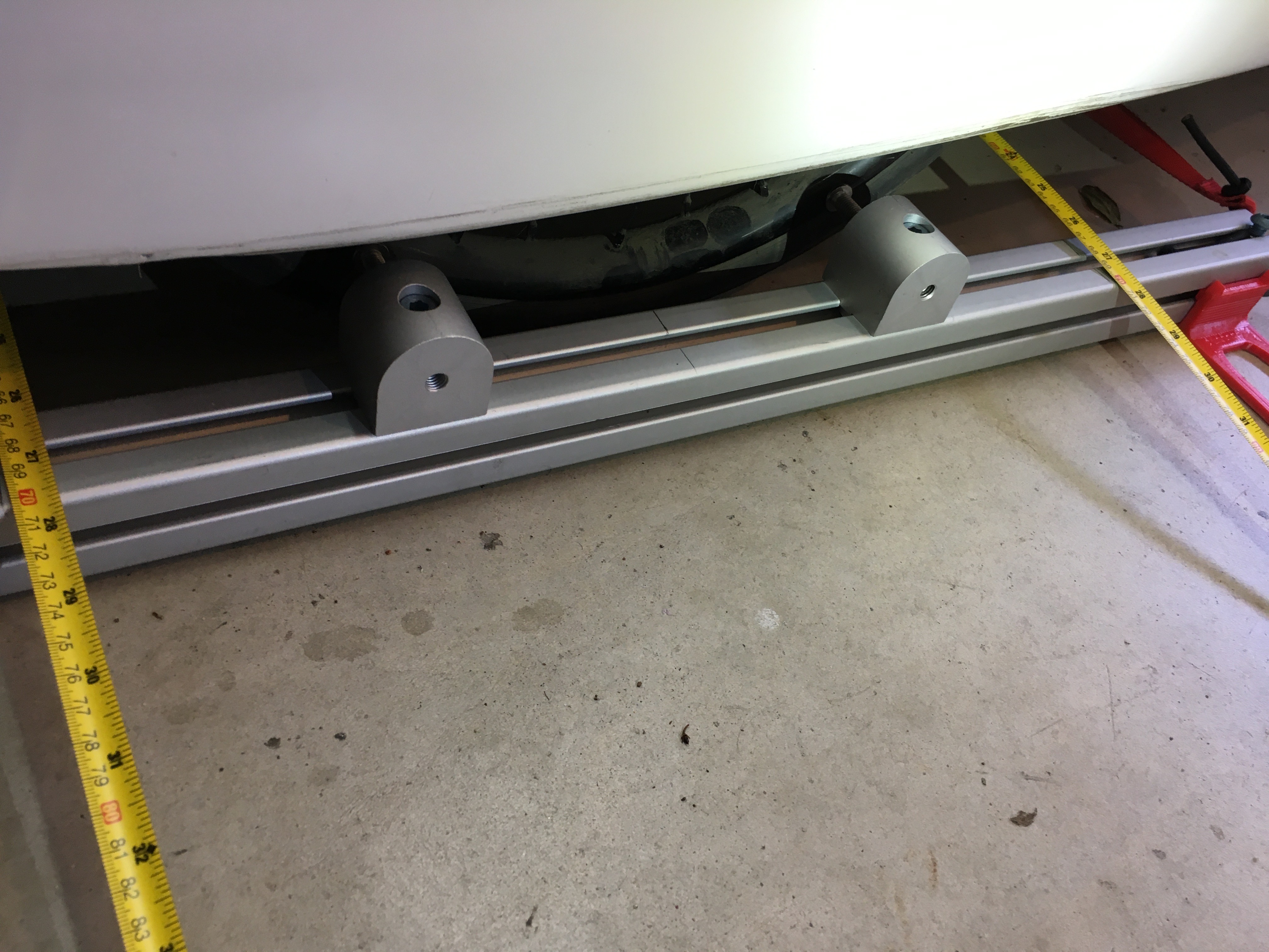
Looking around the garage, I found some 8020 T-slot profiles and some 8020 90 deg threaded nubs. Using these pieces, I concocted this low slung toe gauge. It’s similar to one that I had seen on The Velomobile Observer blog a long time ago. Each bar is placed along a front wheel. The 2 nubs on each bar hold M8 bolts which are screwed into the nub at the same length to form pointers to be pressed against the rim. Using these pointers eliminates any interference from the tires. The ends of the bars are pulled together by the bungee straps that run under the velomobile. These are adjusted with just enough tension to keep the pointers pressed against the rims. The tape measures are used to measure the distance across the bars at the same distance in front of and behind the wheels. So for example, if the wheels are pointed straight ahead, the bars would be parallel and the measurements would be identical and so on. The 4 red plastic pieces are just supports to keep the bars flat on the ground. I’ll probably replace those with some 8020 aluminum pieces that would be more robust.

Here you see the tool used on the Milan SL with its enclosed front wheels.
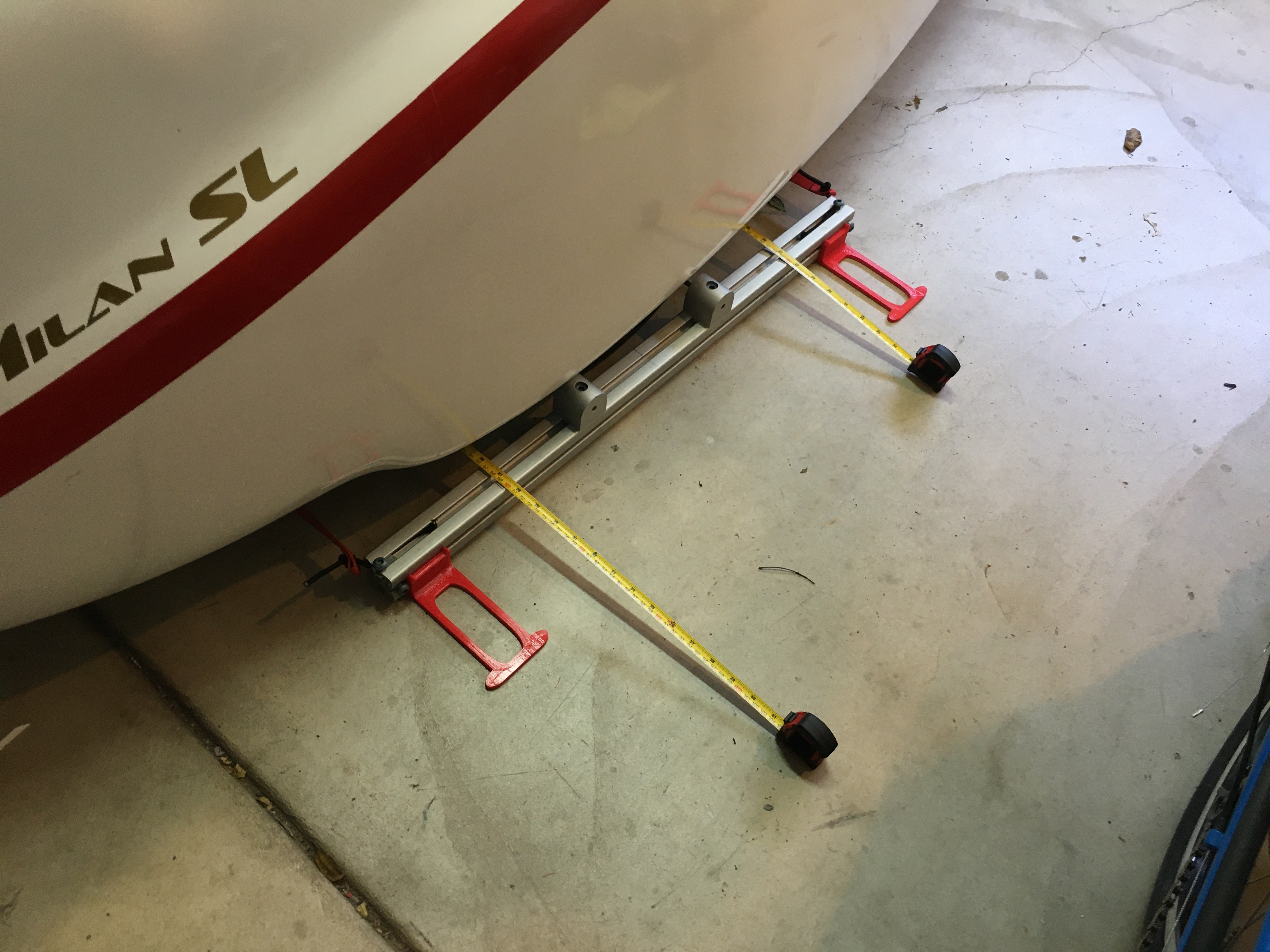
I used the tool today to check the toe-in on the DF and the Milan. I was pretty happy with the ease of use and the repeatability of the measurements. The 80-20 products are very precisely machined so once I had all of the pieces bolted together, I had a tool with no slop and very straight edges.
Here’s a better look at the tool as it stands today – 1 year later. The red plastic feet have been replaced by carbon fiber / PETG 3D printed feet.